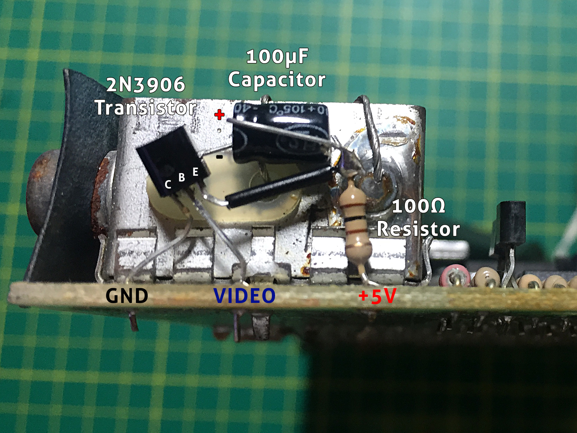
Now I had the Spectrum PCB fully working, I wanted to add a Composite Video modification to round off all the refurbishments. I had already used a neat circuit advised by Andrew Gostling when I repaired a previous machine.

Inverted Emitter Follower Composite Mod
Although that mod works fine, I wasn’t happy with the components being self-suspending. So I set about designing a PCB to house Andrew’s version of the mod, the more usual transistor mod and the simple capacitor mod.
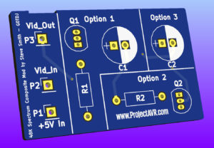
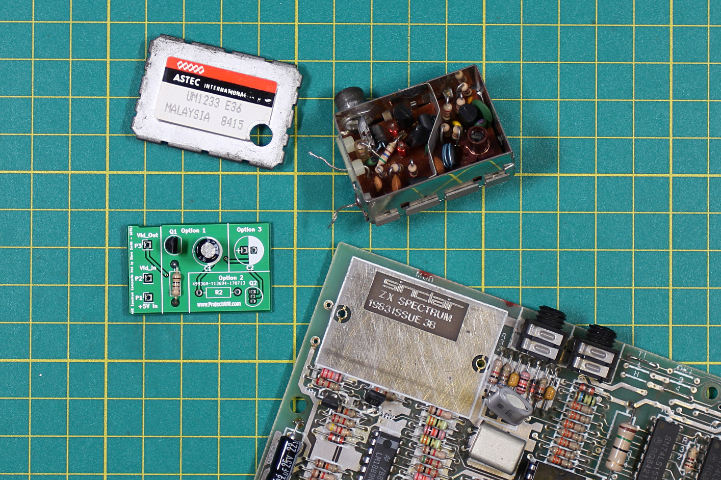
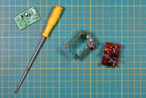
Spectrum 48K Composite Video Mod PCB
The above image is the result. This PCB is made the same size as the one inside the modulator so it can replace the original completely. This is quite involved but I believe it to be very worthwhile. Now I have built one up and found Andrew’s mod to work just as it did self-suspending, I have published the design files for the board on a separate page. I did have a conversation with Andrew around the preservation of the original modulator PCBs. Andrew advocated a mod to be done retaining the circuit board inside the modulator, however, I see no issue with removing the internal PCB, so long as it is kept in a state with which it could be re-installed at any time. As long as the original PCB is removed carefully and without undue force, it can be put into storage for such an eventuality. I will leave it to the reader to decide which option suits them.
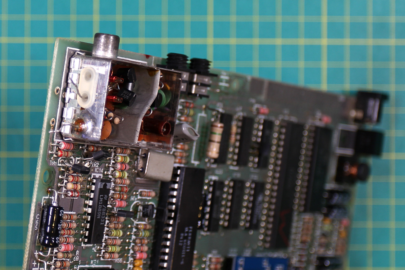
The first step in fitting this new board into the modulator is to carefully extract the modulator from the Spectrum’s PCB. First I de-soldered both the 5V input and Video Input leads from the Spectrum’s PCB.
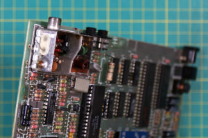
Disconnected Video and +5V Leads
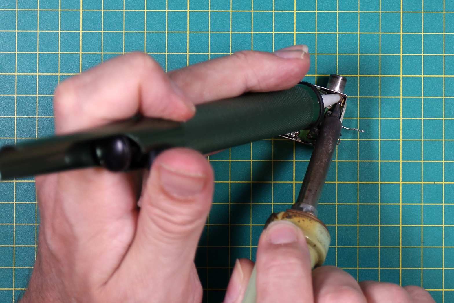
Then it was onto the back to de-solder the large tags on either side of the modulator. These can be a little stubborn and, being heatsinked to the body of the modulator, they do drain the soldering iorn’s heat quickly. A good wattage iron and persistence is the key. When I finally freed the modulator, it came away quite easily and I cleaned the holes left on the board in preparation to replace the modulator box later on. Next, carefully solder in your choice of components to the new pcb. You need only choose one option. In this instance I used Option 1 which is Andrew’s Inverted Emitter Follower design.

Modulator Removed and New Board Soldered Up
Next I needed to remove the old pcb from the modulator. This is held in by several solder spots and the two leads coming in through the side of the case. First I de-soldered the solder spots underneath. this requires a freshly cleaned out de-solder pump. With patience, you can get the desolder pump in place and bring the soldering iron carefully in to melt the solder and trigger the de-soldering pump. I took me a few tries but because there is a defined gap between the PCB and the modulator case, it creates a definite separation when the PCB finally becomes free of the box.
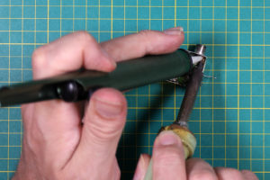
De-Soldering the Modulator’s PCB
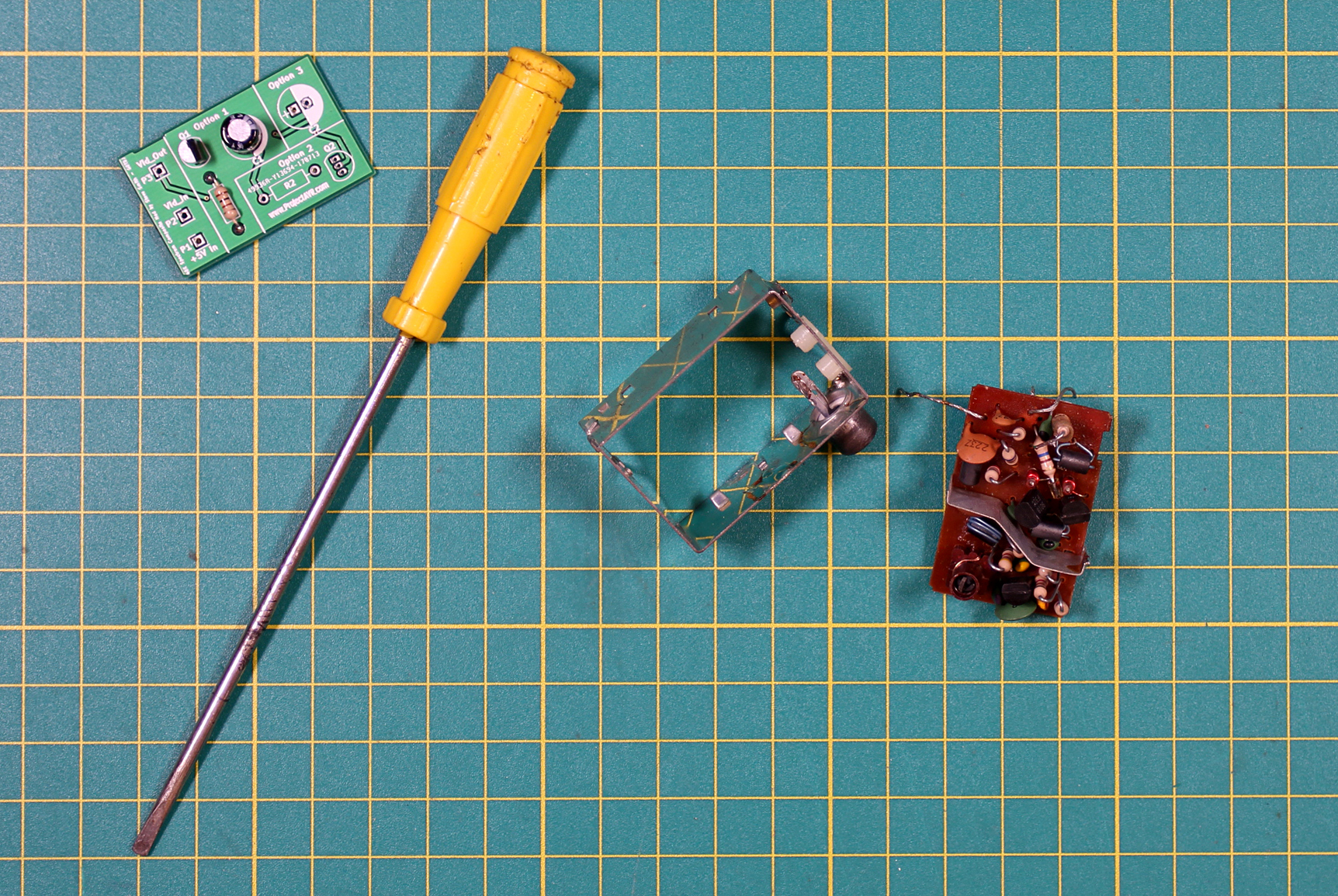
You may find that the screen that goes down the center of the PCB is also soldered to the inside of the Modulator. In this case, just de-solder as you have been doing. This particular one was only secured on the PCB but the previous scrap one I had practiced on was soldered on both sides to the inside of the modulator box. Once I had de-soldered the points underneath, I de-soldered the 5V line and the PCB came out with a bit of gentle persuasion. I boxed the old PCB up in a box, labeled it and placed it into my ‘stock’.
Modulator’s PCB Removed
Next on the agenda was to fit the new PCB. I used Blu-Tack once more, to support the board whilst I got it going. I removed it as soon as two opposing points were soldered.
If I had known how difficult hooking up the video socket to the PCB was going to be, I’d have done that first. If you are carrying this mod out, I’d urge you to save yourself 20 minutes of frustration by connecting the video output point on the PCB to the Spectrum’s output socket before you begin to solder the board into place!
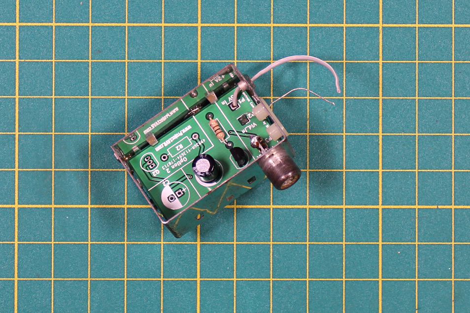
I recycled one of the old wires for the video feed and used a new insulated lead for the +5V. Simply maintain enough length for fitting into the Spectrum PCB once the Modulator box is refitted if you are doing this yourself.

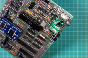
New PCB In Place and Connecting Leads Attached.
I could now refit the Modulator box to the Spectrum’s PCB. This was pretty straightforward having prepared the tag holes earlier. Once the box was in place, I soldered the flying leads in place too.
Modulator Box In Place and Connections Made
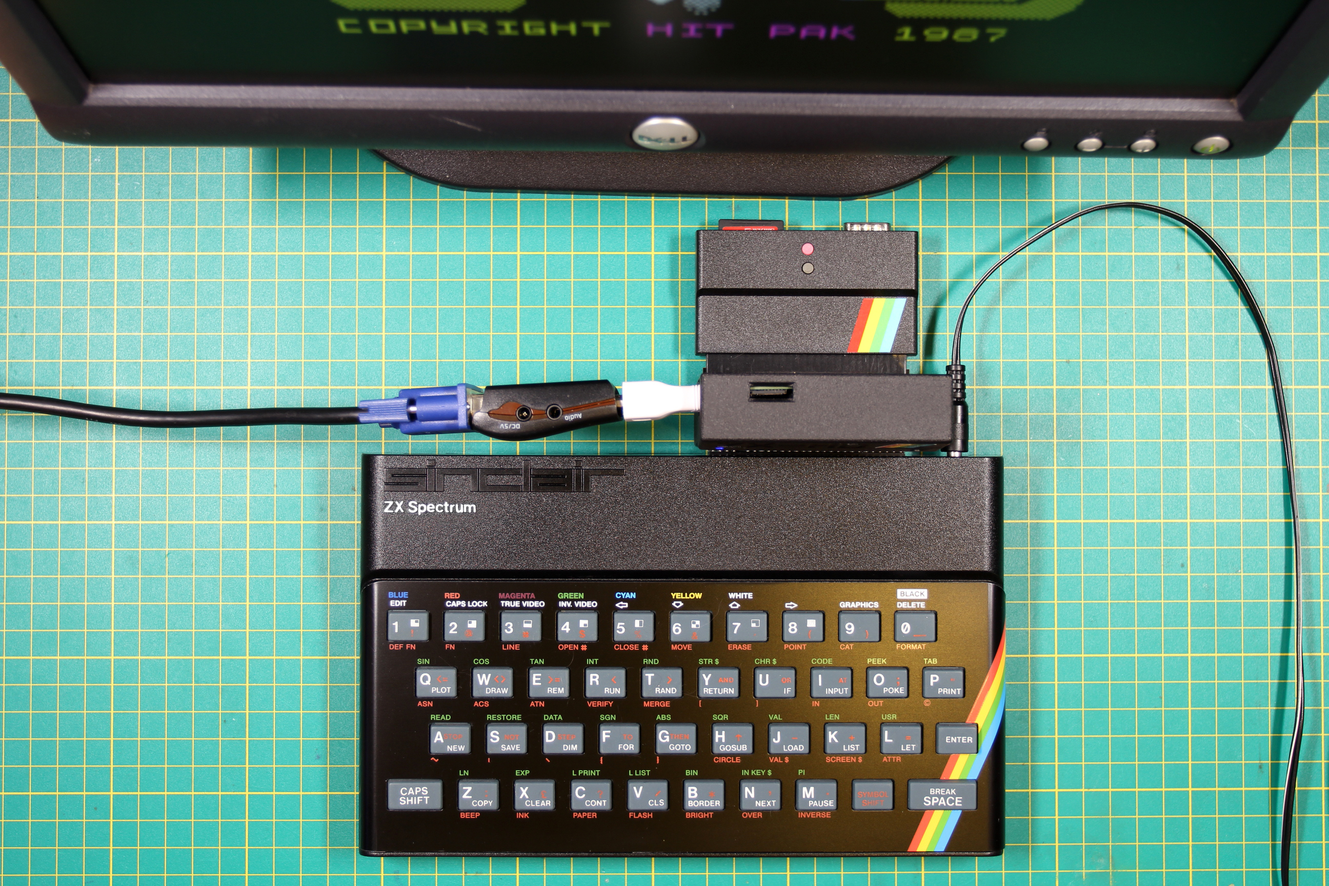
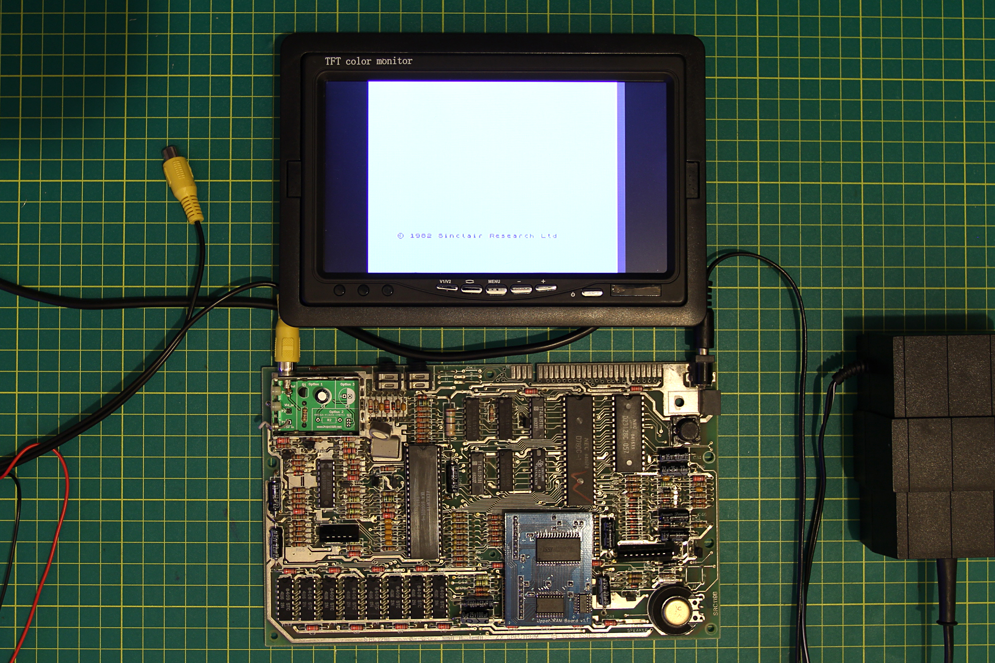
Now I’d got the Modulator box back in place with all the connections made (The ground being connected via the Modulator case), it was time to test the Composite Output. Unfortunately, as regular readers will know, I haven’t got a large Composite Monitor. However, I have got one of the small 7in models meant for installing in cars. This makes a reasonable test monitor, although would be a little difficult to use for any length of time.
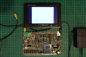
Composite Video Test
The image above, shot on my iPhone, shows the board with Composite Output working on the bench. After testing this, I gently pulled the slack cable on the +5V lead into the Modulator box and replaced the Modulator’s cap.
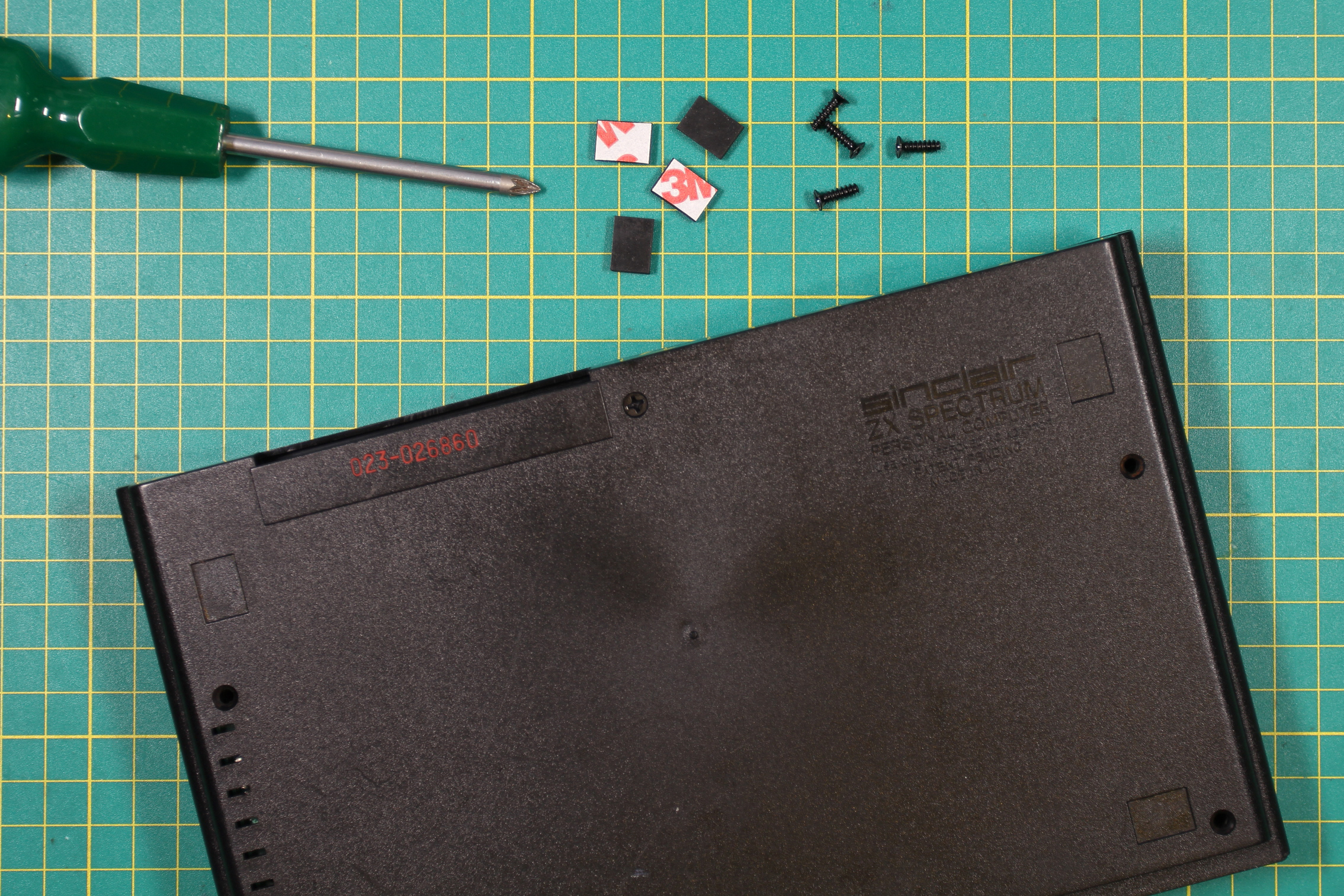
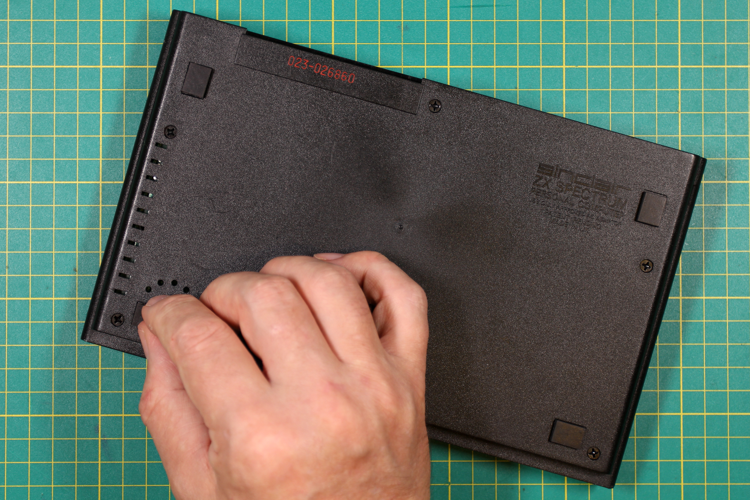
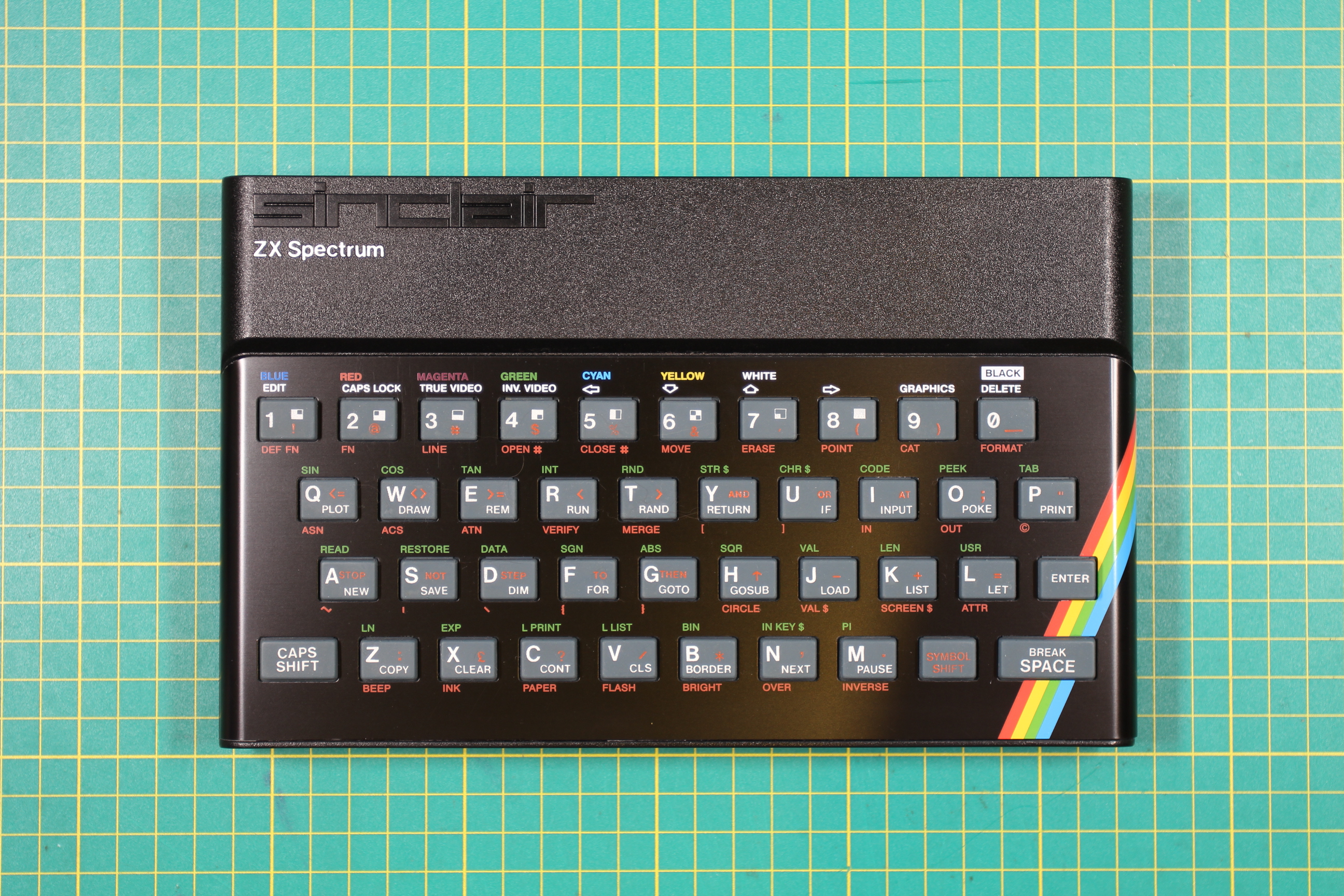
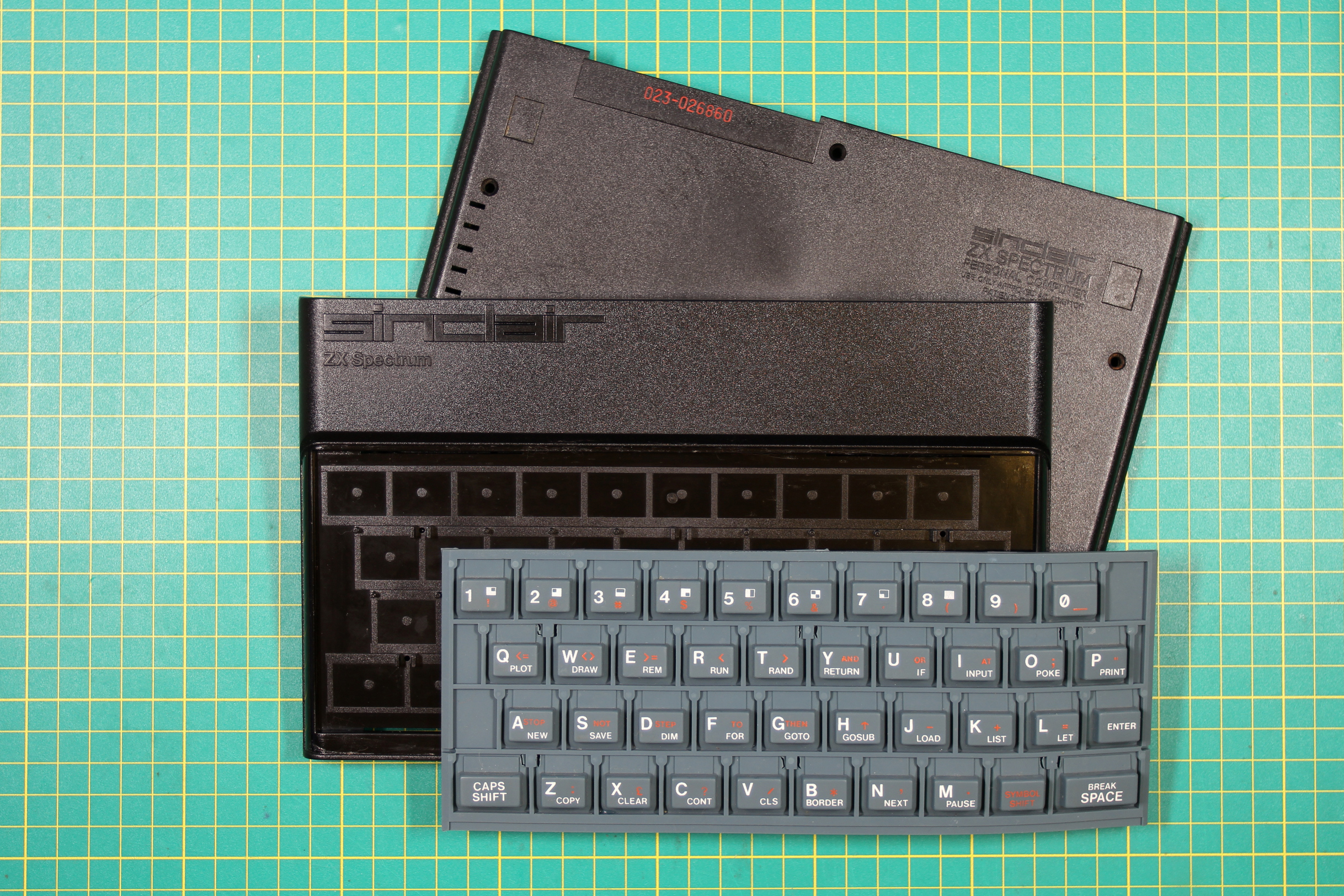
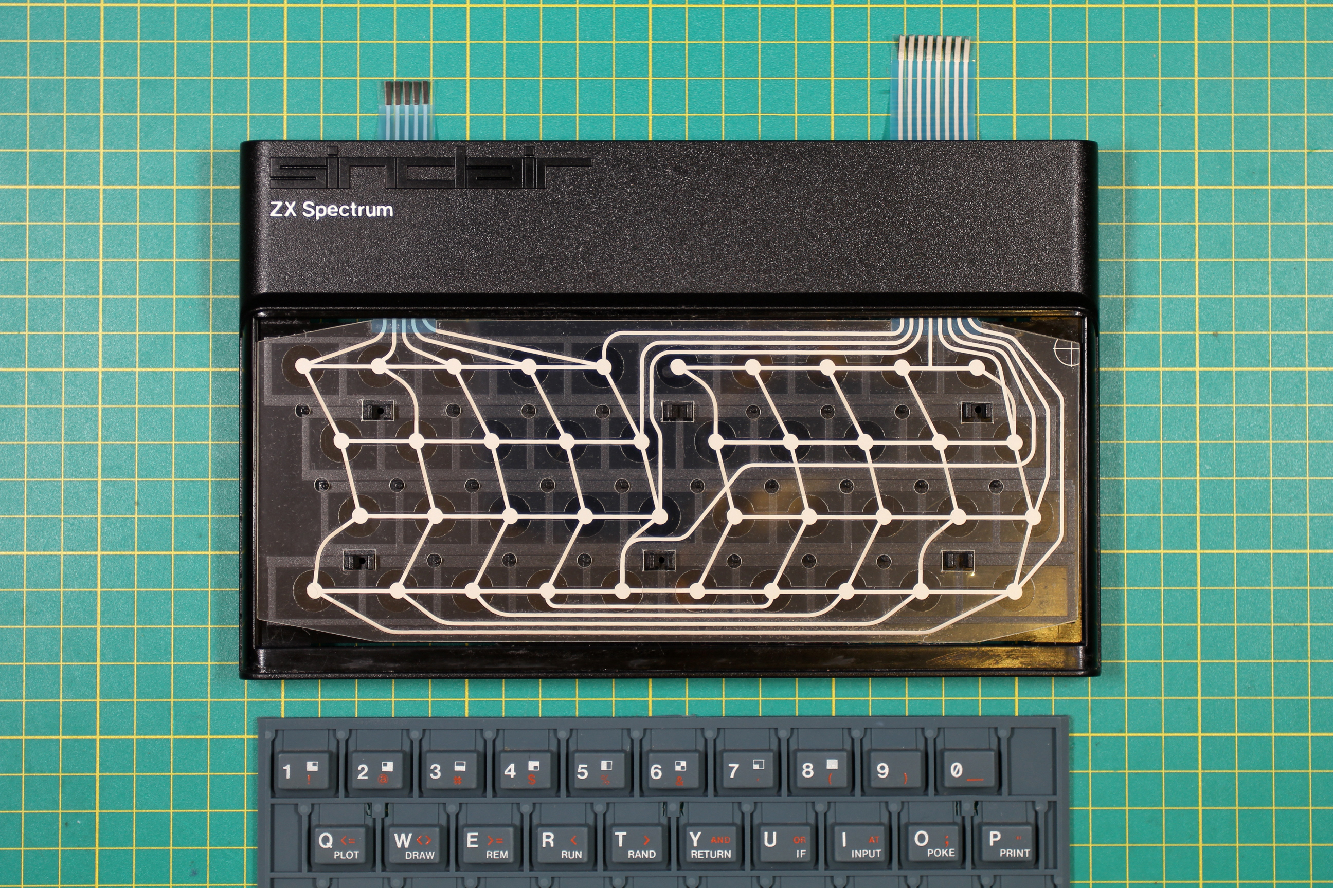
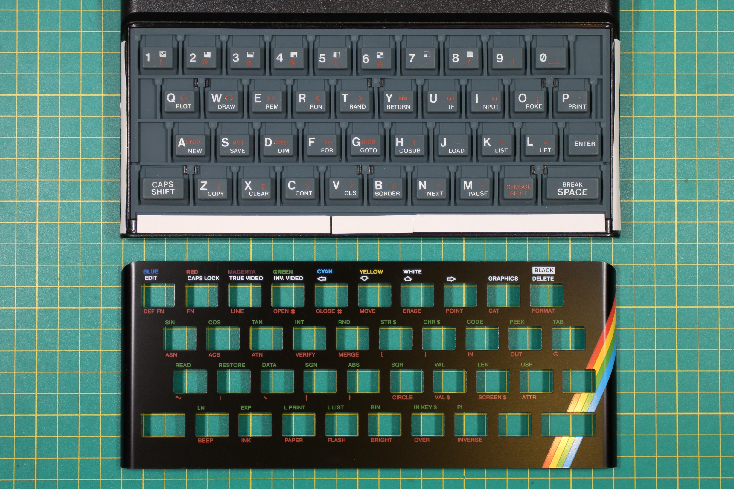
Next, I turned my attention to the cosmetics of the Spectrum’s Case.