![]() minDUINO v1.5, v1.6, v1.6k and v1.7 – Are Small Footprint, Educational Arduino™ clones.
minDUINO v1.5, v1.6, v1.6k and v1.7 – Are Small Footprint, Educational Arduino™ clones.
This webpage holds all the design files and information to make and program the minDUINO v1.5, v1.6, v1.6k and v1.7 boards. The designs are released under Creative Commons Attribution Share-Alike. This means that you can freely copy the designs and adapt them for your own purposes provided you attribute the design to ‘ProjectAVR – Steve Smith G0TDJ’ and use the same license for your adapted designs. Full information on the Creative Commons website. The intention is to make these designs Open Hardware. The v1.5, v1.6, v1.6k and v1.7 boards have all been assembled and tested by myself. Although I don’t attach any warranty or fitness for purpose. If you wish to use the designs you may do so freely at your own risk.
If you look online you will find a myriad of Arduino™ clones of all different shapes and sizes. So why would I want to produce yet more? The truth is, I love designing things. I was also inspired to create these boards because my friends daughter, I will call her Amelia, has found an interest in electronics. Amelia’s father and I have given her several things to build, commercially available kits, but I wanted to encourage her to experiment. Since I have a familiarity with AVRs and Arduino™, I elected to follow that path.
The minDUINO is designed to be easy to assemble, so it is a two layer through-hole design, and has no SMD components. It has headers for FTDI, ISCP and port breakouts. Another project I designed was VAYU-NTX, a High Altitude Balloon Tracker. As expansion for this, I designed two small daughter boards for experimenting with. I followed a similar idea with the minDUINO and placed the breakout headers together. Later on, I may design a bespoke board but its just as easy to use stripboard/perfboard paired with the appropriate header socket.
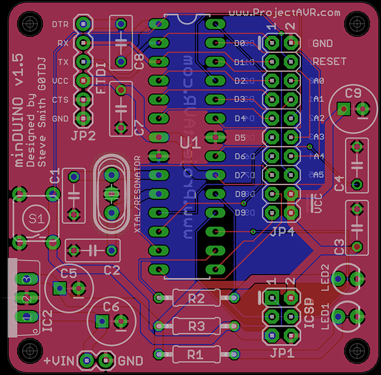
minDUINO V1.5 Eagle Preview
I had the boards fabricated by the excellent Hackvana. The gerber files necessary for this are linked below. I have been using Hackvana for a while and they have fabricated several boards for me. Their customer service is second to none and the end result is a high quality, professional PCB that would be at home in any commercial equipment. All you need to do is supply Hackvana the Gerber Zip files and they will fabricate your boards for you. I would recommend that you have a chat with Mitch who runs Hackvana before ordering. You can chat to him live (Timezone permitting) on IRC – A live text chatting system long established on the internet. Just sign in with your name or a nickname and fill in the CAPTCHA.

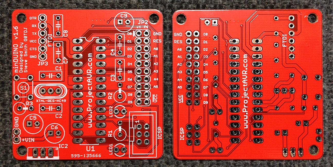
minDUINO v1.4 prototype Front & Back
As you can see from the above image, the boards look exactly as they do in the gerblook preview. Once I was in receipt of the boards, I set to work building one up to check all was well. I started with the lower profile components and worked up to the larger ones. All in all it took around 45mins to do a slow careful job. The hardest part was bending the ATMEGA328’s pins in slightly to get it in the IC Socket!
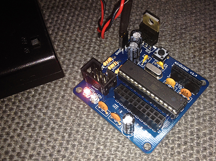
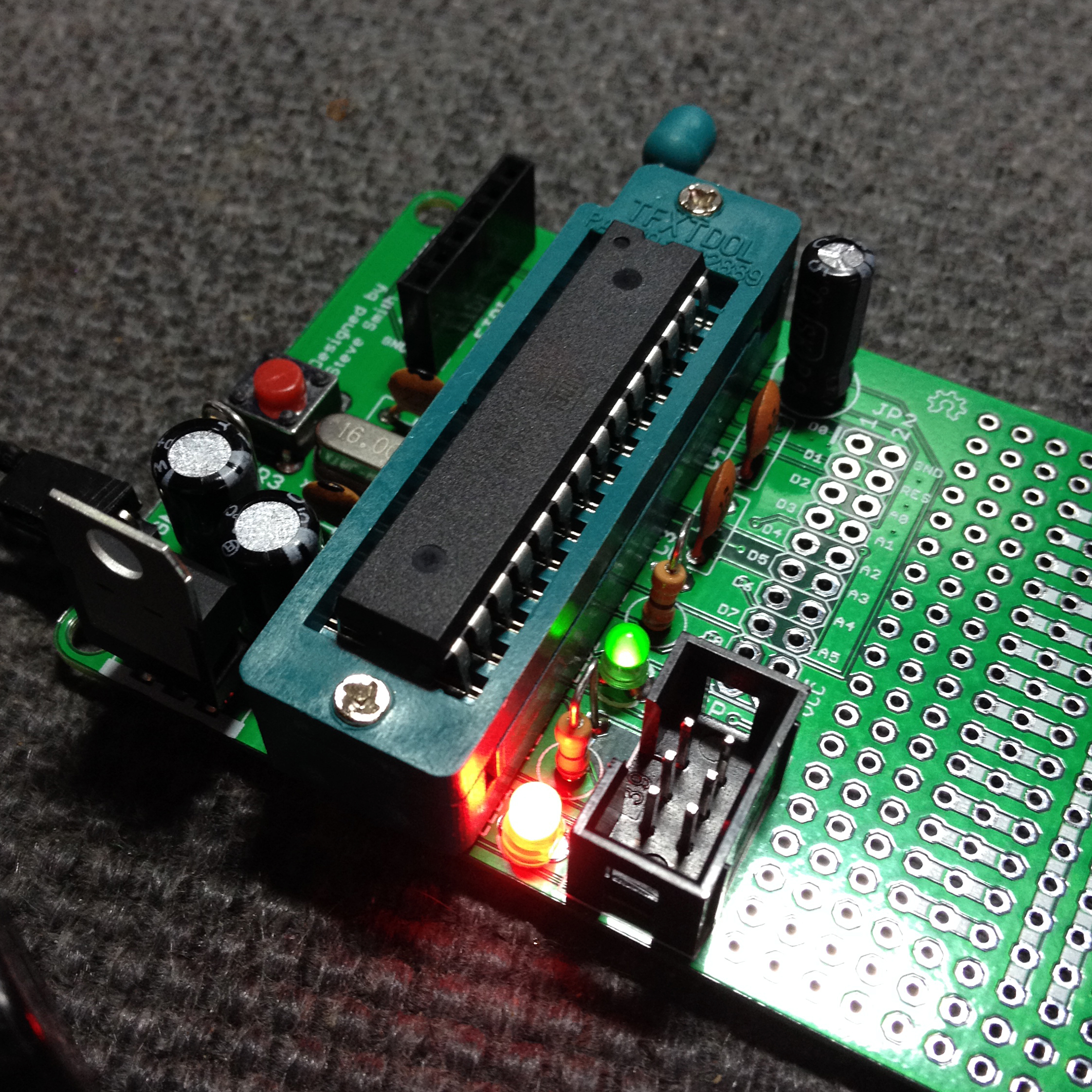
minDUINO prototype v1.4 assembled and powered up
The board has two LEDs, one red, as seen above, for power indication and one green for testing. I chose to connect the green test LED to pin D10 (Physical pin 16) because it is capable of PWM output and I particularly wanted to demonstrate the use of PWM to Amelia. I used a shrouded connector for the ICSP connection which matches the plug from my USBASP programmer.
Here are all the files necessary for minDUINO v1.5 fabrication:
- minDUINO v1.5 Eagle v6.3.0 .SCH schematic file
- minDUINO v1.5 Eagle v6.3.0 .BRD board file
- minDUINO v1.5 Gerber .ZIP file
- minDUINO v1.5 Image files .ZIP
- minDUINO v1.5 Parts List .PDF file
- minDUINO v1.5 Schematic .PDF file
The entire directory of resources is available at minDUINO v1.5
minDUINO v1.6
I have designed a variant that can accommodate a 28-pin ZIF (Zero Insertion Force) socket to aid programming. The minDUINO v1.6. The idea is to have one v1.6 board that you would use to program chips with a variety of methods to suit your work environment and use a v1.5 board for actual projects. There’s nothing to say you can’t use the v1.5 board for programming but if you are intending to continually insert and remove chips, having a ZIF socket available is a lot less hastle. I had to shuffle some of the components around on the v1.6 board to make room for the ZIF socket but it’s the same circuit.
minDUINO v1.6 Front & Back
If your ATMEGA328 chip has an Arduino™ bootloader or another variant such as Optiboot, then you can use an FTDI module connected to the FTDI Port as shown.

minDUINO v1.6 FTDI Programming
You can use flying leads rather than plugging the module directly in if preferred. This would be necessary for other modules which have an alternative pin configuration. The labels on the board are designed for the pictured FT232 module and the TX & RX lines have already been reversed. Remember also that the notch (Pin 1) on the IC goes towards the handle of the ZIF Socket. Further details on programming below but be aware of the board version numbers.
Here are all the files necessary for minDUINO v1.6 fabrication:
- minDUINO v1.6 Eagle v6.3.0 .SCH schematic file
- minDUINO v1.6 Eagle v6.3.0 .BRD board file
- minDUINO v1.6 Gerber .ZIP file
- minDUINO v1.6 Image files .ZIP
- minDUINO v1.6 Parts List .PDF file
- minDUINO v1.6 Schematic .PDF file
The entire directory of resources is available at minDUINO v1.6
Here are all the files necessary for minDUINO v1.6k fabrication:
- minDUINO v1.6k KiCad v4.0.6 .SCH schematic file
- minDUINO v1.6k KiCad v4.0.6 .PCB board file
- minDUINO v1.6k Gerber .ZIP file
- minDUINO v1.6k Image Files .ZIP file
- minDUINO v1.6k Parts List .CSV file
- minDUINO v1.6k Schematic .PDF file
The entire directory of resources is available at minDUINO v1.6k
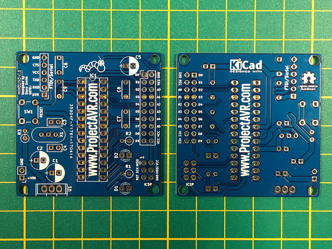
minDUINO v1.6k Front and Back
From time to time, there will be full kits of parts available on Tindie. All the necessary information for building can be found on this page.
For all the previous versions of the minDUINO (v1.5, v1.6 and v1.6k), I have designed a simple tray that the built board can be fitted to in order to avoid shorts on conductive surfaces. You can find the STL ready for slicing and 3D Printing on Thingiverse.
minDUINO v1.6 on tray
minDUINO v1.7
The minDUINO v1.7 was a bit of an afterthought. I reasoned that it may be convenient to have a prototyping area available without resorting to a breadboard for semi-permanent or permanent use.
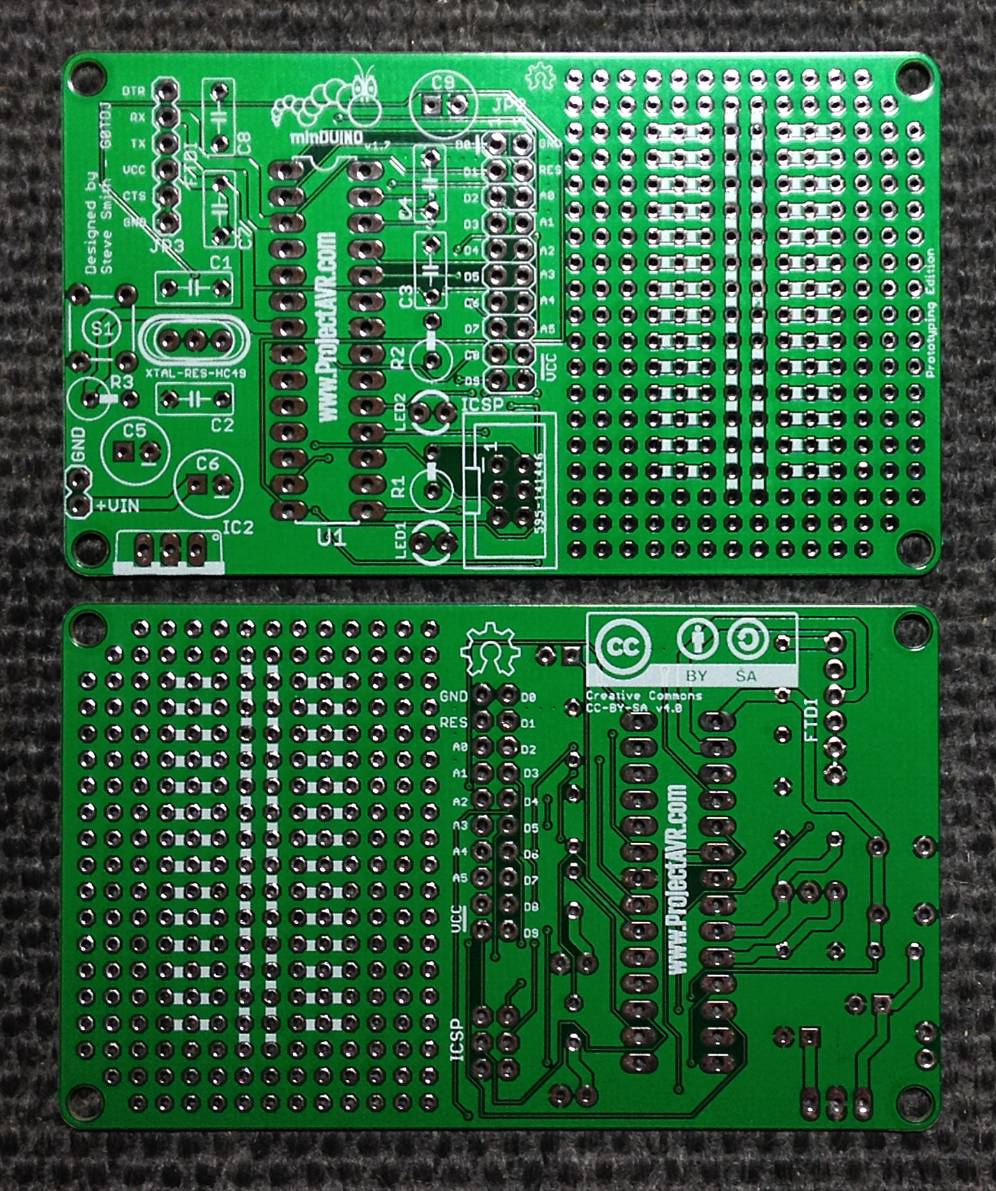
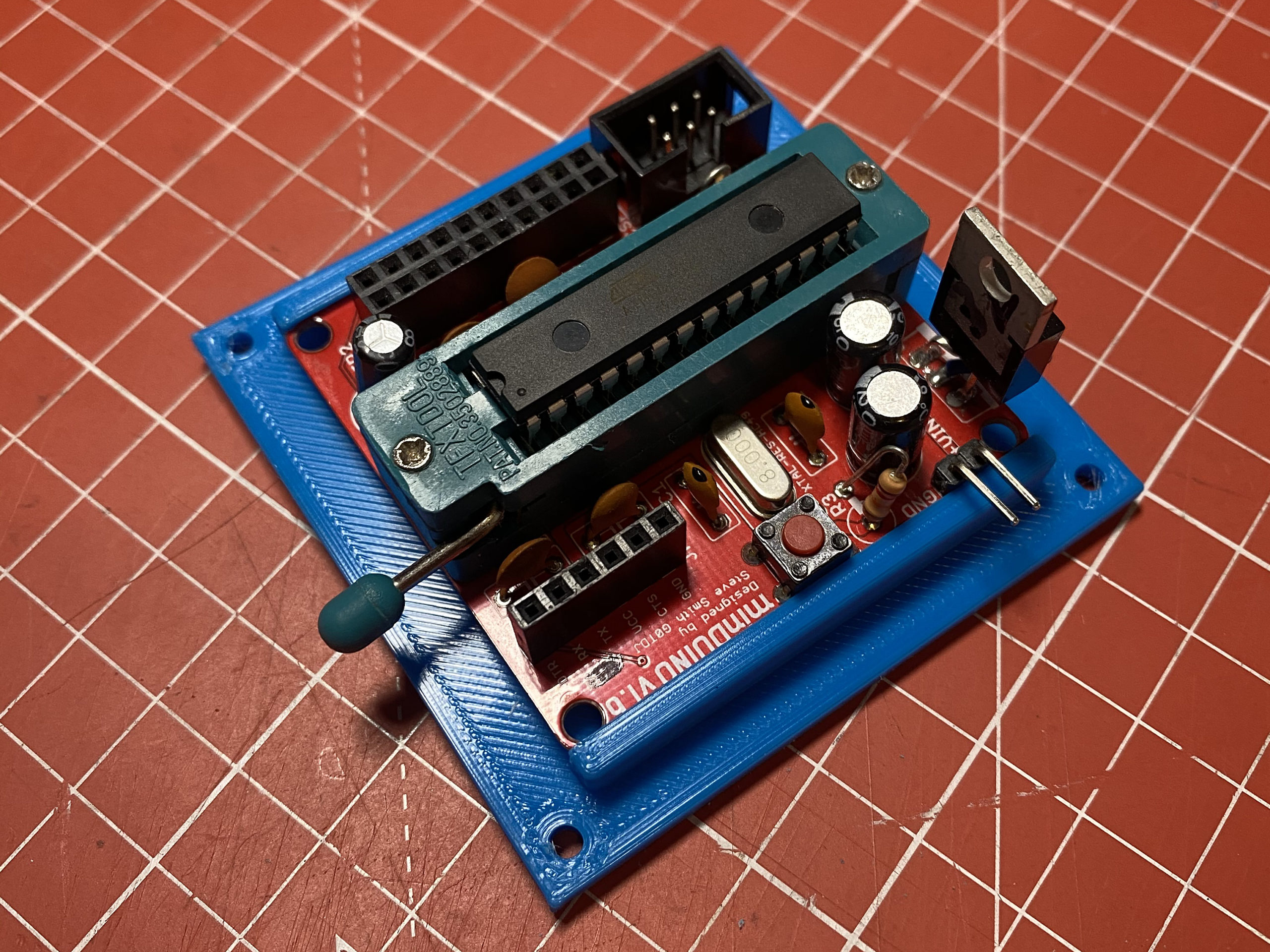
minDUINO v1.7 Prototyping Edition
I added an area on the right hand side of the v1.6 board, connected a pair of rails in the middle and several sets of three contacts to facilitate connection to DIP chips. The ports that are broken out to the header from the ATMEGA328 are easily linked in to the prototyping area with short wires.
minDUINO v1.7 Prototyping Edition Built & Tested
I have configured the board in the image above specifically for programming, hence the ZIF socket but a normal IC socket would probably be more appropriate for most other uses.
Here are all the files necessary for minDUINO v1.7 fabrication:
- minDUINO v1.7 Eagle v6.3.0 .SCH schematic file
- minDUINO v1.7 Eagle v6.3.0 .BRD board file
- minDUINO v1.7 Gerber .ZIP file
- minDUINO v1.7 Image files .ZIP
- minDUINO v1.7 Parts List .PDF file
- minDUINO v1.7 Schematic .PDF file
The entire directory of resources is available at minDUINO v1.7
Programming
There are several ways to program the board. An FTDI module can be used if a bootloader is present or an AVR programmer via the ICSP port.
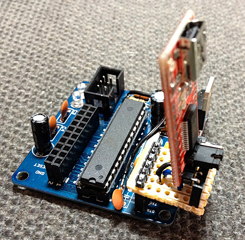
The minDUINO v1.4 prototype required an FTDI Adaptor due to an error on the board.
The FTDI module shown here is one using the FT232 chip. On the minDUINO v1.5 board, I have reversed the TX and RX connections so this FTDI module will fit straight into the board.
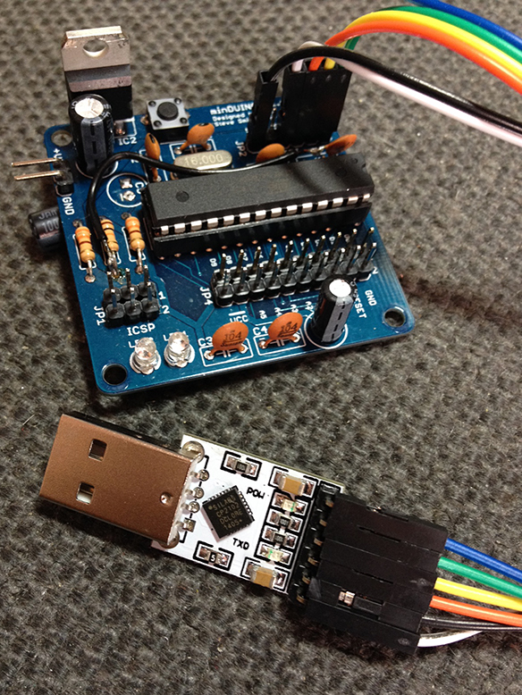
Alternative CP2012 FTDI Module and minDUINO v1.4 prototype
Programming via the ICSP Port can be facilitated with a wide range of programmers including the AVRISP MkII, USBASP, USBTiny ISP And even a re-purposed Arduino UNO.
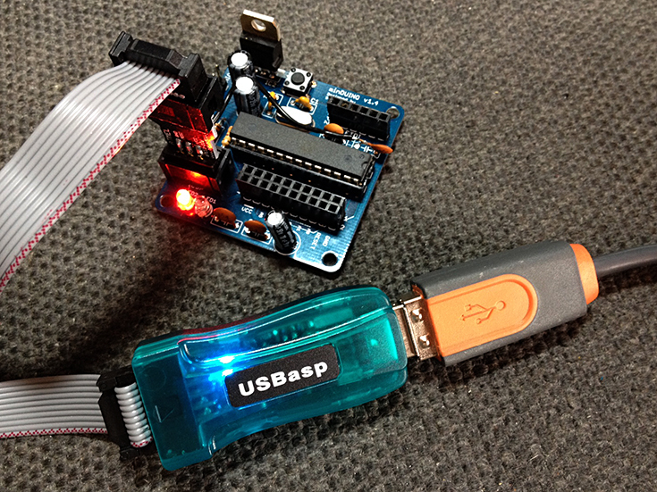
USBASP with minDUINO v1.4 prototype
For those who are new to the world of Arduino™ and Microcontrollers and need something a little more accessible, I’d recommend The Shrimp. This is a breadboad/stripboard design not unlike the minDUINO but much easier to build quickly. Building it on a breadboard is ideally suited to tinkering with the circuit, adding bits and experimenting. There are also instructions on how to program The Shrimp via a CP2102 FTDI module. Once you are more familiar with Arduino and Microcontrollers, you might like to build a minDUINO.
[UPDATE 21/05/2014]
I am now in receipt of an official Atmel AVR-ISP MkII programmer. It is a very nice piece of kit in a tidy box. It comes with a good quality USB A/B cable and a CD containing technical data and Atmel Studio (Although a new version of Atmel Studio has just been released).
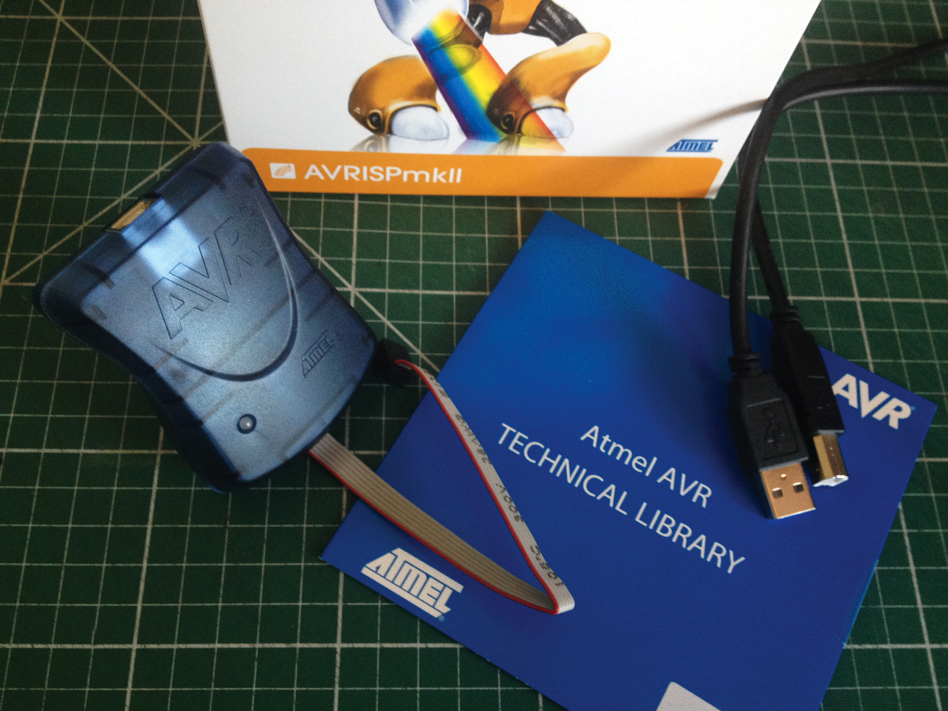
AVRISP MkII
The programmer and Atmel Studio work well together but with the slight issue of making the USBASP clone programmer useless. The drivers for these devices are mutually exclusive so you can only have one installed at a time. I have chosen to stick with Atmel Studio because it’s a much more professional tool than the Arduino IDE and I have been wanting to learn how to use it anyhow. Also, you can download a plugin for Atmel Studio which allows compiling of Arduino ‘Sketches’ and up load to devices. This is available in Atmel’s Gallery.
[UPDATE 28/05/2014]
I have discovered a small error in the circuit preventing FTDI operation. C8 is connected to the wrong side of R2. A temporary fix is to only solder the side of C8 that connects to the FTDI header and connect the other side directly to the opposite side of R2. The same line as the AVR Pin 1. I will be updating the information with mniDUINO v1.5 soon which has a few refinements as well as a proper fix for the FTDI issue.
[UPDATE 30/05/2014]
After much confusion, I have discovered another issue. As well as the capacitor problem noted above, the TX and RX pins are also reversed for the FTDI connections. I had ordered a pair of cheap CP2012 chipped FTDI adaptors only to find that the header did not match up with the connections I had placed on the minDUINO board. I then ordered an FT232 type adaptor which was in line with my connections. Neither worked.
There were a lot of variables in place here. My lack of Serial Device knowledge, Several ATMEGA328s without boot-loaders and the procedure to upload. I have now updated the text above with programming instructions for the two FTDI modules. minDUINO v1.5 design files will be available soon.
[UPDATE 31/05/2014]
I’ve now completed the updates to the minDUINO v1.5 design. Amended a few details on the schematic and on the board layout itself, I’ve added the option for using a three pin resonator instead of a crystal and capacitors, moved the two electrolytics associated with the 7805 regulator (In case I decide to make a board with a ZIF socket) and swapped the LED designations. This is in addition to the fixes for the FTDI routing and mistake on the reset line. I’ll be publishing the new v1.5 files when I have assembled them.
[UPDATE 16/06/2014]
I am currently awaiting the v1.5 and v1.6 boards arrival from the fabricator for checking. I will publish the v1.6 design files here once this has been done.
[UPDATE 16/06/2014]
I am now in receipt of the minDUINO v1.5 & 1.6 boards. I have built both and released all the design files. They are linked above. Please let me know if you have any fabricated and what you are using them for. You can contact me via: steve(at)projectavr(dot)com

minDUINO by ProjectAVR – Steve Smith G0TDJ is licensed under a Creative Commons Attribution-ShareAlike 4.0 International License.