The Morse Practice Oscillator boards finally arrived! Sometimes I dispair my orders will ever get from China to the UK without incident. I think I may use the DHL option more often.
Anyway, having unpacked the new boards, I built the Oscillator up. No hitches, just the usual technique. Start with the low profile components first, resistors, dodes etc. And work up from there. This time, I had the base plate board to add.
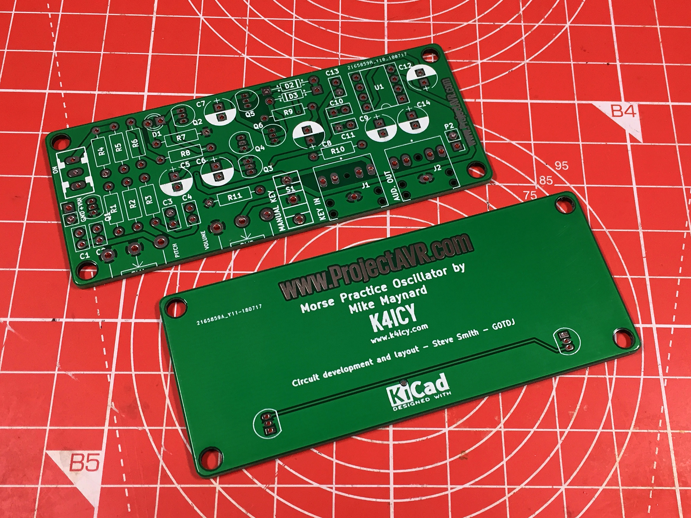
Oscillator and Base Boards
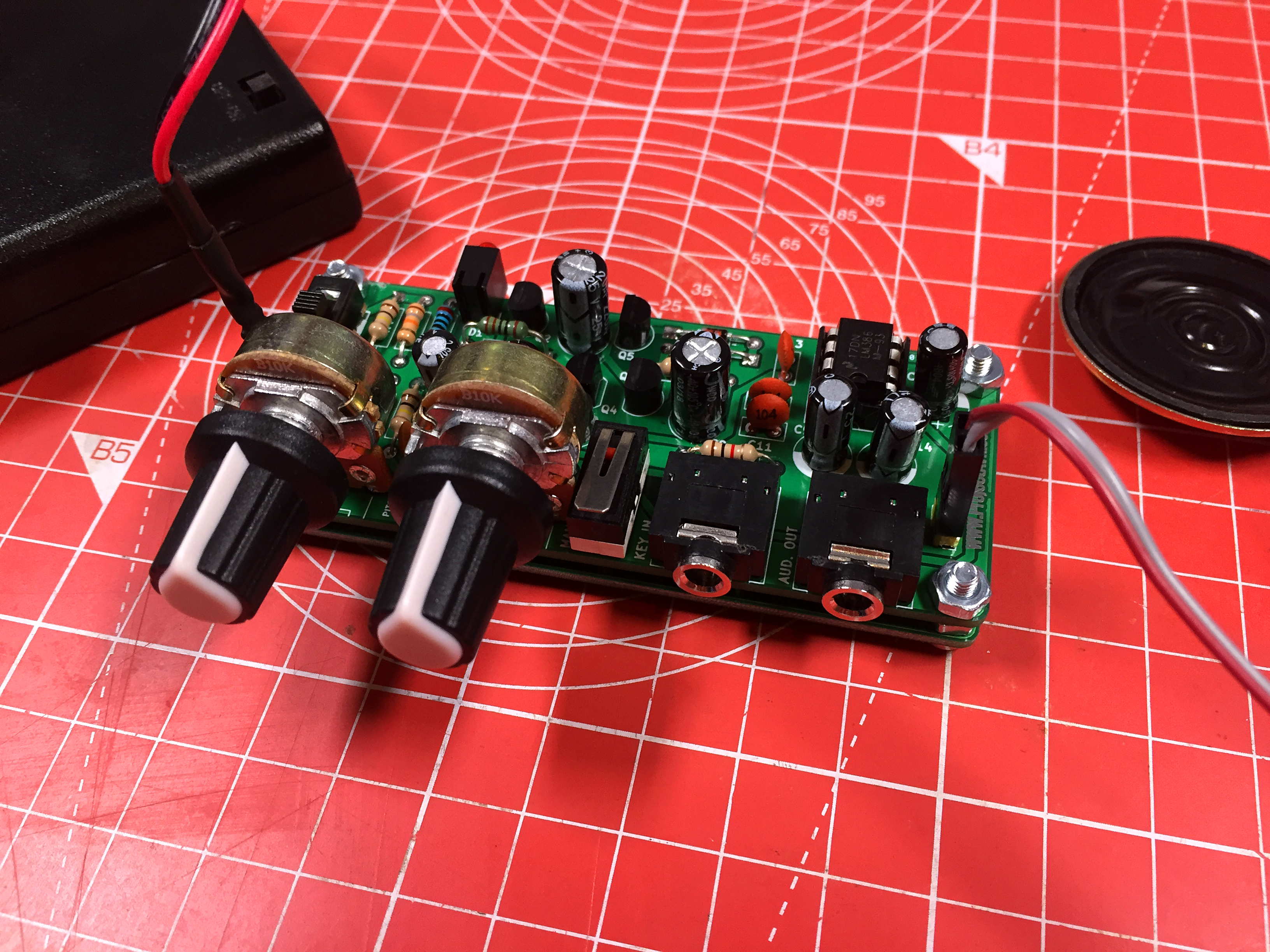
Completed Oscillator and Base Board
Two things I didn’t fully consider; One was to leave clearance for the nuts that hold the base plate on. It is obscured in the image above, but the left hand front nut can’t be added since the Pitch potentiometer is too close. Secondly, the on board Micro Switch Morse Key is just too close to the Volume potentiometer to be useful. It works fine but needs to be moved.
I also discovered, I’d made a mess of the micro switch footprint somehow. The pins were .5mm too close to the center. I did manage to force it in by bending the pins to test the board but I have since corrected the footprint.
As expected, the oscillator works perfectly, whether it be monitored with earphones via the socket, or have a speaker connected to the output header. The LED for visual comms is a little dim but I suspect that a regular LED (rather than right angled) might be a better bet. I’ve yet to test this.
Meanwhile, I’ve redesigned both boards. The base plate now has only two single pin headers. This is instead of the two transistor footprints. This provides a connection to create a ground copper pour. I have also shuffled the components around on the oscillator board to enable the micro switch to be placed on the far right, for unobstructed use. This required moving the key socket to the rear but also gives enough room to move the potentiometers, allowing room for the missing fixing nut.
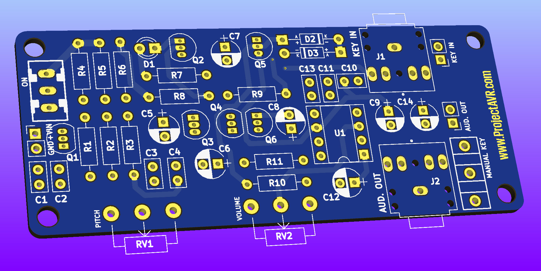
CW Practice Oscillator v2.04 StAR Edition
Having now taken another stab at the design, I’ll get them fabricated and see if they are the final version!
As I was writing this entry, another board arrived; A 7 Decade Resistor Substitution Board. This is one of a few PCBs I have designed specifically for the students I help teach every week.
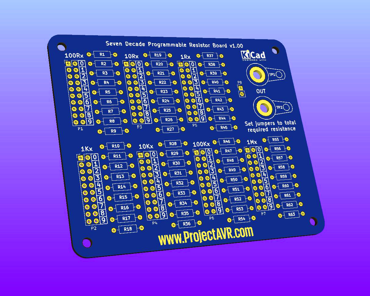
7 Decade Programmable Resistor Board v1.00
The idea is that the students get plenty of soldering practice and also end up with a useful item to take home and use in their own electronics experiments.
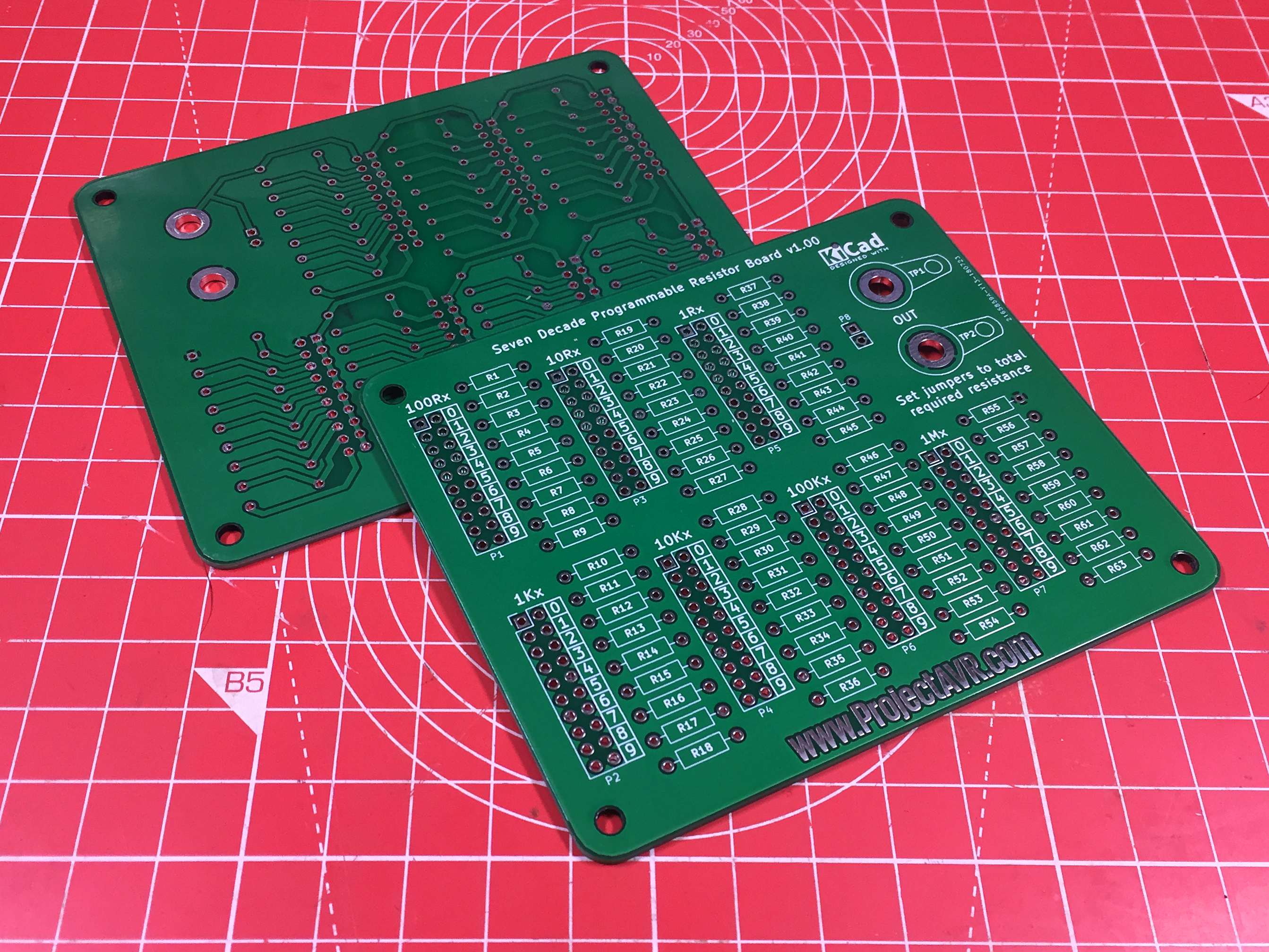
7 Decade Programmable Resistor PCB
Another one of these simple PCBs is a 555 LED Flasher. This should redily be built in under an hour, even for a beginner.
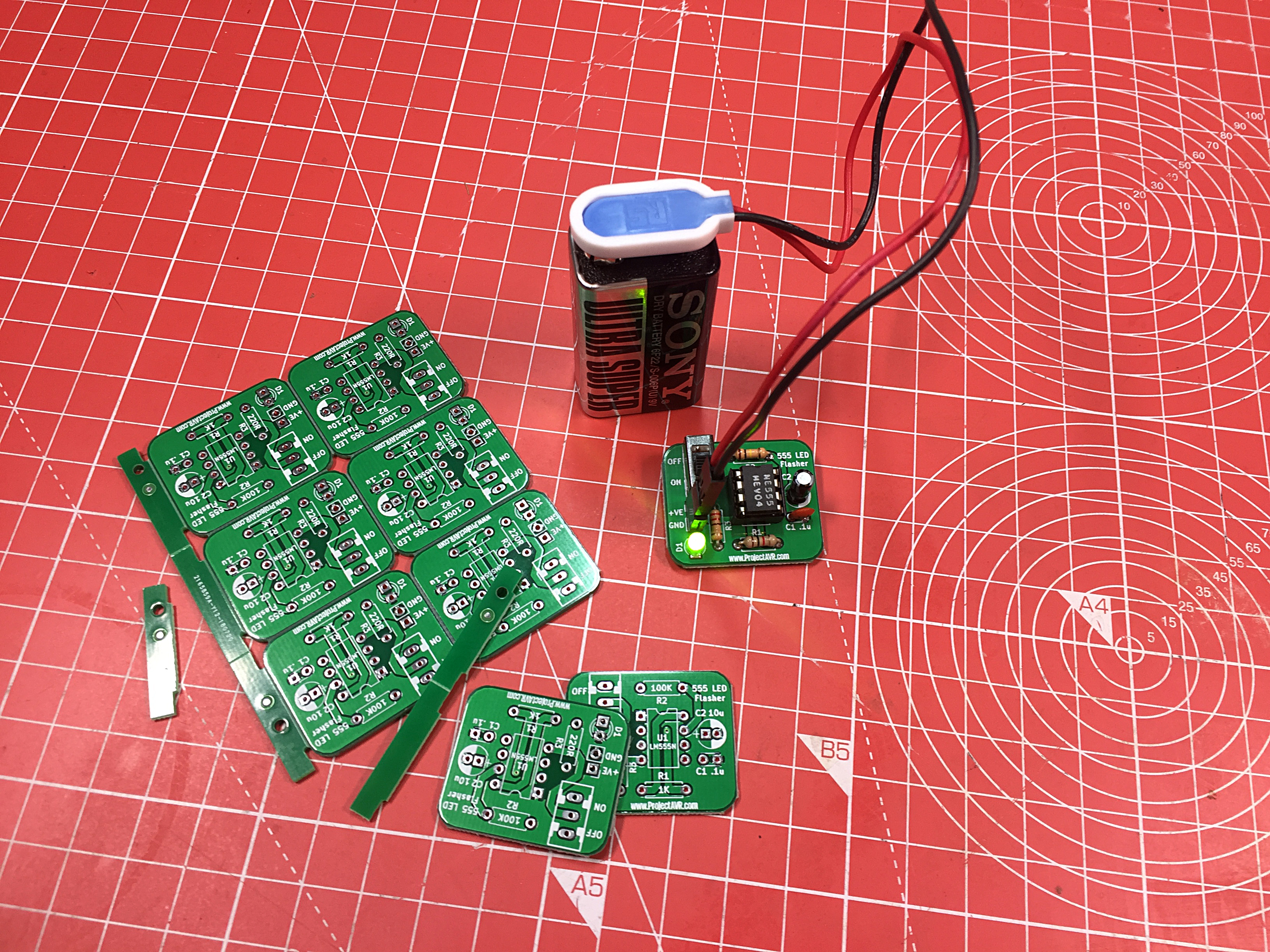
Simple 555 LED Flasher and Panelised PCBs
Here seen operating along side the panelised PCB. All the boards in this post were fabricated by JLCPCB.com I recently discovered that not only do they supply 10x boards smaller than 100mm x 100mm for $2 (Plus Delivery)*, but if you can panelise the boards within 100mm x 100mm, including 10mm border for ‘V’ grooves, you end up with more boards for your buck. There is a function on the order screen for this avoinding having to do it manually.
*Make sure the one single PCB’s size bigger than 20mm x 20mm otherwise a surchage is added.
Note: 555 LED Flasher and 7 Decade Programmable Resistor Substitution Board design files are now available on Non-AVR Projects Page.