Programmable USB Foot Switch Box
A short while ago, I wrote a post in the blog about a Programmable USB Foot Switch box I designed to help me be a more effective player in Battlefield 5. Now, having tested it, I can publish the files. I did fall foul of one ‘gotcha’ during development. I ordered a bunch of Pro Micro clones from China, only to find that they have a different footprint to the one I’d used in my prototype! Silly me thinking they would be the same 🙂
Construction is easy and flexible for this project. The hardest thing is giving access to the 8-way DIP switch for programming ASCII Characters. Of course, you could program the four memories and leave it at that if you so chose.
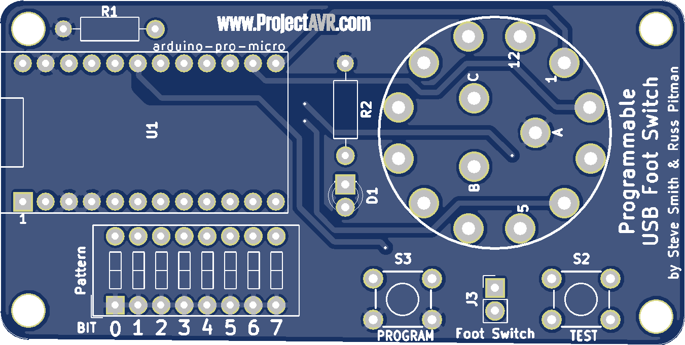
I started with the header pins on the Arduino Pro Micro. These, I later soldered directly into the PCB. I moved on to the DIP switch, the resistors and LED and finally, the tact switches and rotary switch. I specifically wanted a rotary switch but the only one I could find was a 4-way, 3-pole one. Two poles aren’t used in this case. The Tact switches are 17mm high, so that they protrude through the case. I prototyped it with usual size ones for testing.
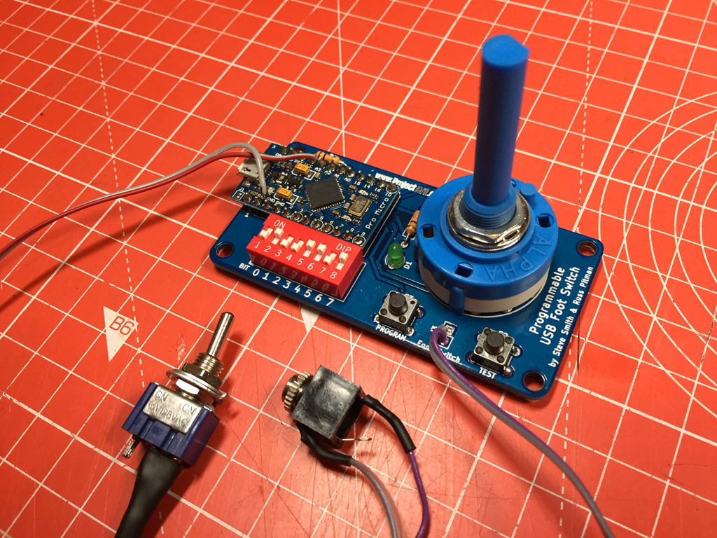
As you can see in the above image, I jerry-rigged a toggle switch to add enable/disable functionality, but that was only really needed whilst testing so I removed it before casing the design.
The board is held in place on the case with the rotary switch thread. Once it has been tightend, it provides enough support for all of the board. I drilled appropriate holes by printing out the pad layout and positioning it on the case top and using a bradawl to mark the center positions of the devices requiring holes. The circular holes were easy. The hole to access the DIP switch was slightly more difficult, but since the case is plastic, I gradually cut away with a sharp craft knife. Be careful to always keep your fingers away from the business end of the blade! I have found this out to my cost in the past.
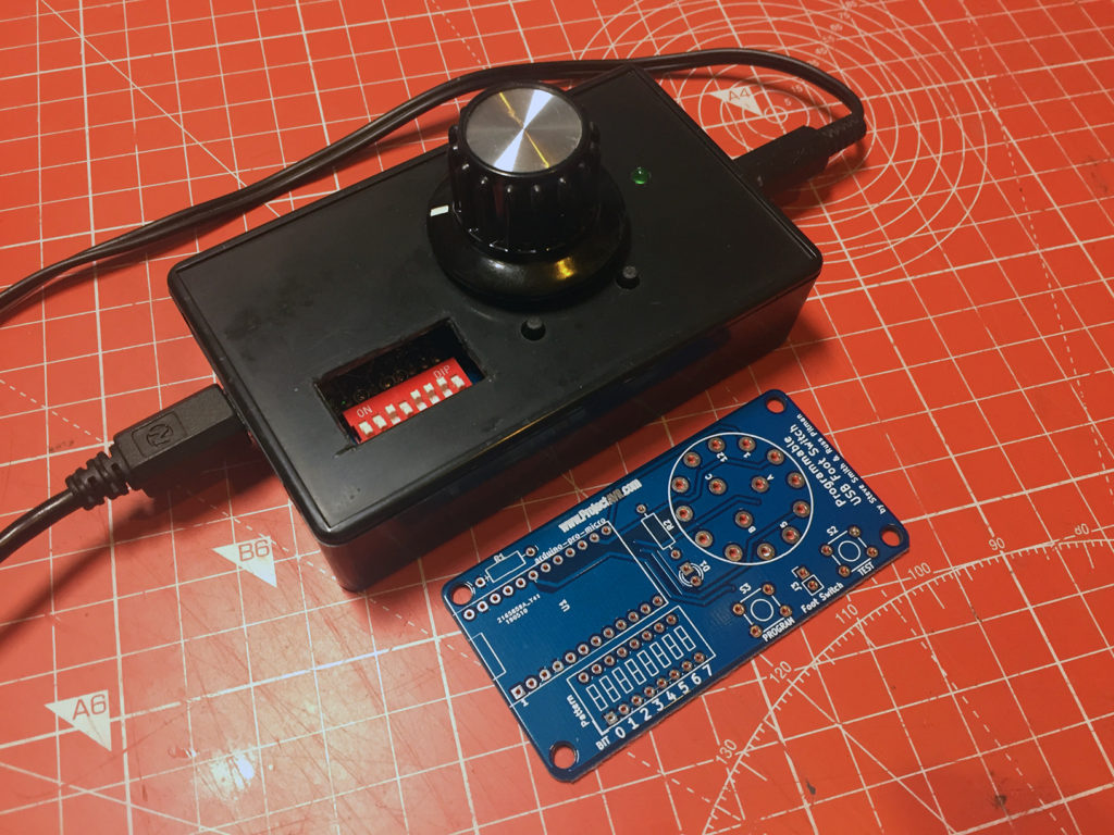
The knob I used on the prototype was a little large, but it was the only one I had to hand. I have since replaced it with a smaller one.
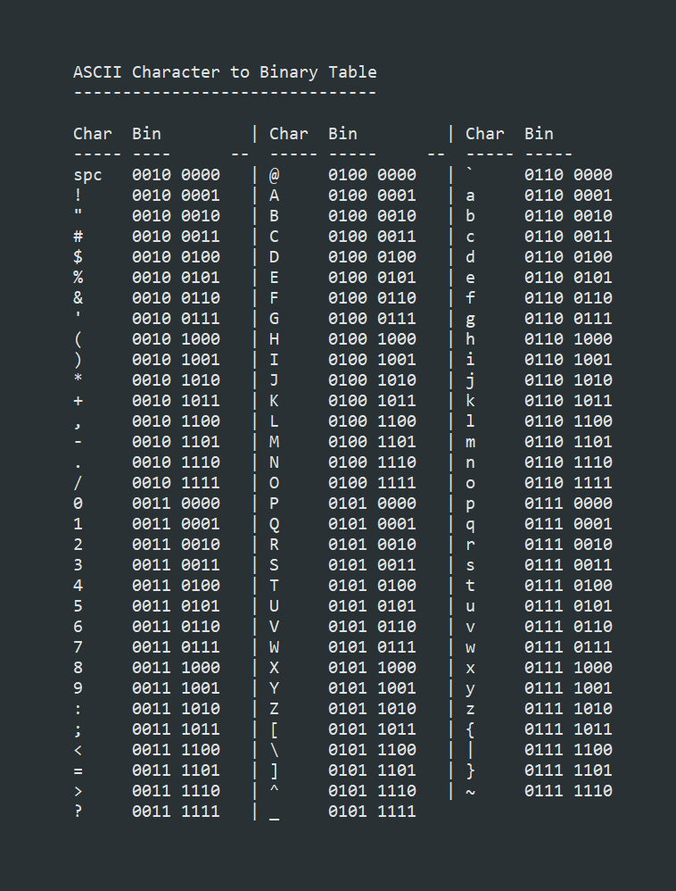
To program the device, you select the binary code of the character you wish to have in the memory position selected by the rotary switch and press the ‘Program’ button. The LED should flash three times to confirm programming. Henceforth, each time you depress the foot switch, the device will send that character to your computer as if it was by a keyboard. Since it uses the ‘Keyboard’ library, it will repead the keypress in the same interval you have set in your operating system.
Here are all the files necessary for fabricating the Programmable USB Foot Switch:
Programmable USB Foot Switch Schematic .PDF file
Programmable USB Foot Switch KiCad files
Programmable USB Foot Switch Gerbers .ZIP file
Programmable USB Foot Switch Arduino .INO file
This is a fairly easy project to construct and programming is easy since it is based on an Arduino Pro-Micro (Leonardo). I had mine working in no time and I have since built a second unit so I can use both feet whilst playing!
Morse Code Decoder v1.01
Whilst operating with my ‘Radio Ham’ hat on, I quite enjoy engaging with contests to give points away. I particularly enjoy CW (Morse Code) contests for their speed and efficiency. The problem is that there are many stations sending at way over the speed that I can copy. My usual technique is to sit on a station’s frequency and listen round and round until I have built up the callsign and captured the latest serial number and then call. This takes lots of time.
I had the idea of using a Morse Decoder to aid me in giving points away in contests, so I did a search online and found a likely circuit. It is a very simple design, just a potential divider across some AVR pins. The most complicated bit is the display connections!
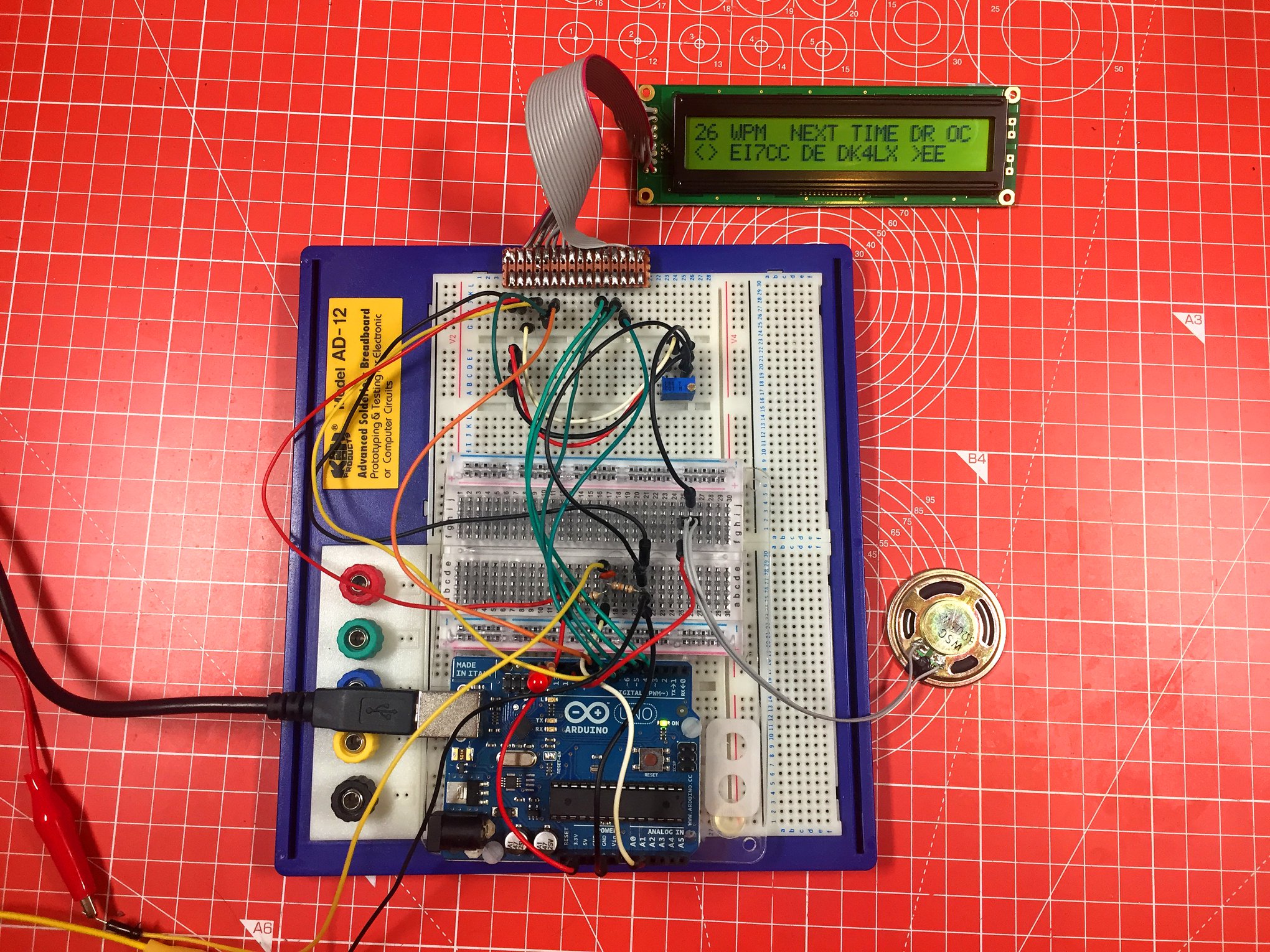
Breadboard Prototype CW Decoder v1.00
I prototyped the circuit up and used a 2×24 character line display, rather than the 16×2 line display as was recommended in the build instructions. The circuit worked sporadically when plugged into my TS-590S radio leading me to remove the capacitor from the input. This seemed to make the circuit a lot more reliable. Your mileage may vary, I recommend you try the circuit with and without the capacitor and see which works best for you.
The next step was to design a board. I used a previous design of AVR circuit as a base and designed a small board. For some reason, I configured the display header in a really strange way, leading me to re-design the board with a straight through connector for the 24×2 line display connector. It would be a simple job to wire up an alternative display and change the relevent option in the code to suit.
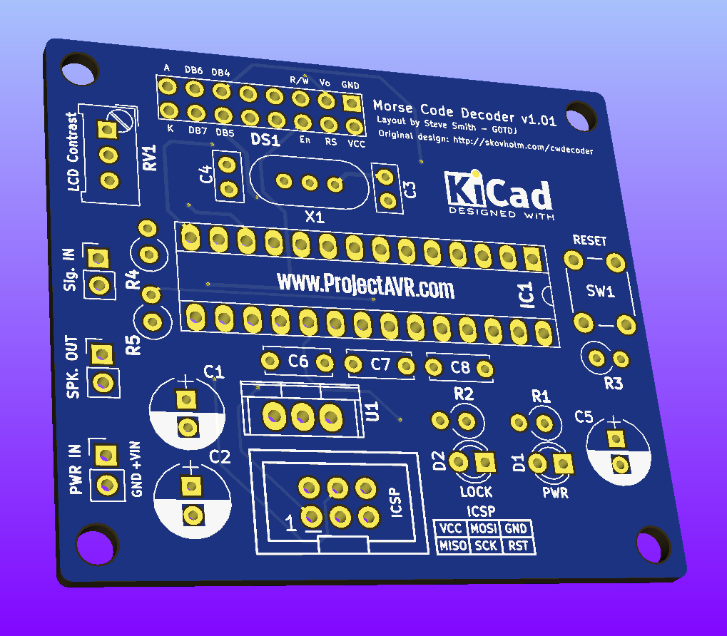
CW Decoder v1.01
On this newer version of the board, all the relevant connections for the display are labelled. I chose to use a 7805 linear regulator for both it’s familiarity to me and the fact that I have a number ‘in stock’. The only slight issue I have found with this version of the board is that the display contrast pot, RV1, is a little close to the header when plugged in. It can be gently bent away if required but be very careful not to put too much pressure on it. Since this is usually set and left alone, it shouldn’t be an issue.
I included a reset switch to clear the display. When in operation, the device sometimes decodes random noise in the form of Ts and Es. With the reset switch, you can clear down and have the device recalibrate the speed of incoming code.
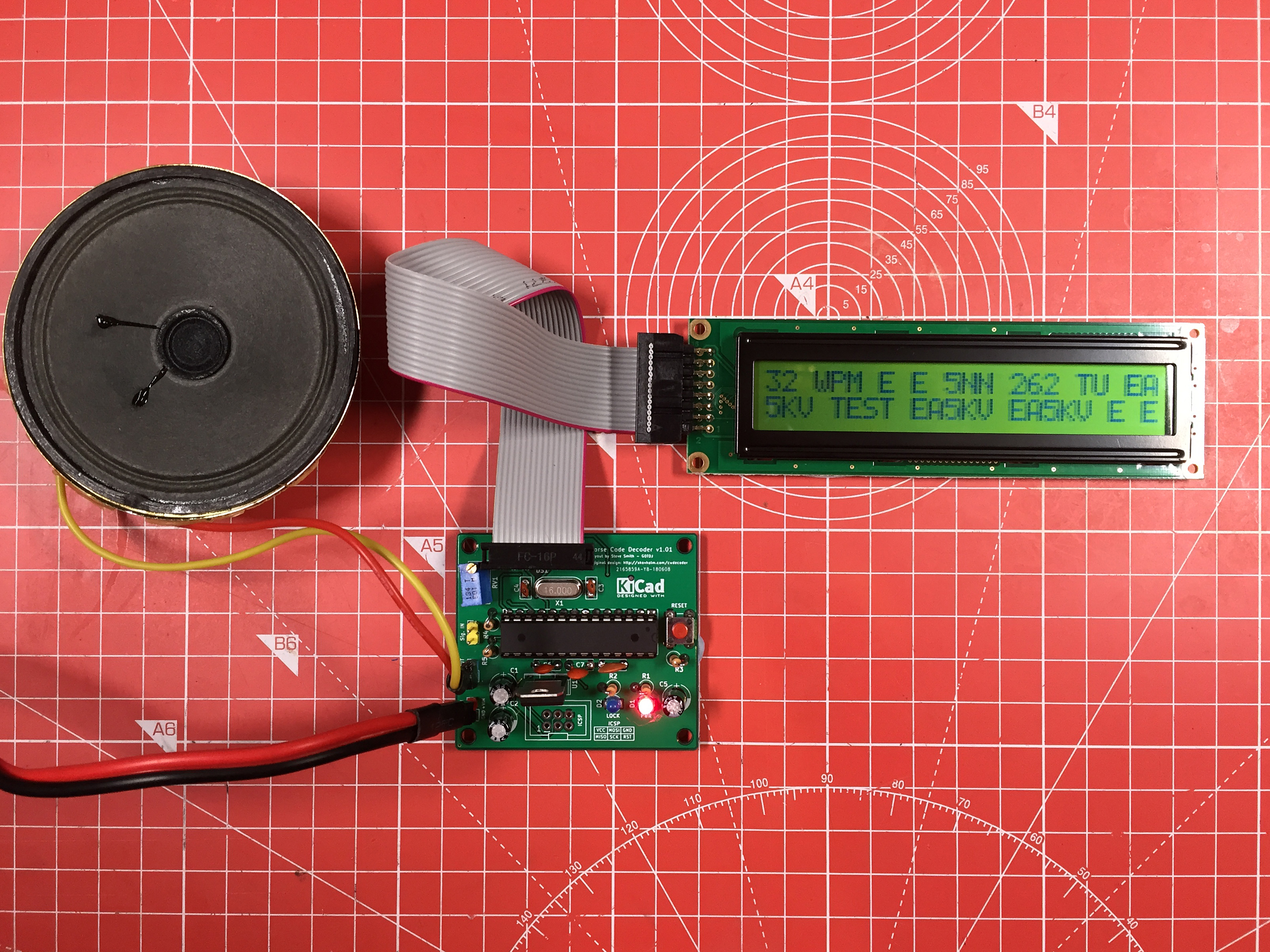
CW Decoder v1.01 in Operation
I have yet to box the board, display and speaker but the above image shows the CW Decoder after just having received some contest Morse Code at 32 Words Per Minute. I think it would be useful if the Morse speed could be inverted on the display, I will look into the code and see if this is possible.
Here are all the files necessary for fabricating the Morse Code Decoder v1.01:
- Morse Code Decoder v1.01 Schematic .PDF file
- Morse Code Decoder v1.01 KiCad files
- Morse Code Decoder v1.01 Gerber .ZIP file
- Morse Code Decoder v1.01 Sketch .INO file
- Morse Code Decoder v1.01 Images .ZIP file
- Morse Code Decoder v1.01 Parts List TXT file
The entire directory of resources is available at: CW_Decoder v1.01
If you build one of these devices, please remember to edit the code to reflect the size of display you use.
TZXDuino Compact
Because of the Spectrum Next, I got interested in Sinclair Spectrums after a long (15 year) break. I have acquired a few of the original models and enjoyed reaquainting myself with the Spectrum system and programming. Although I have a DivIDE and other such interfaces, there’s nothing like the nostalgia you get when you load an original program from tape.
Although I own several Spectrum tapes from the old days, there are files available online in TAP and TZX formats which can be played as if you had the original tapes. These are redily loaded into Spectrum emulators but not so easily into the real thing. However, a couple of very clever guys, Duncan Edwards and Andrew Beer came up with a device to do just that. The TAP or TZX files are copied onto a Micro SD Card and placed in the device which, via a menu, you can play the files into a real Spectrum machine. The device can be used with several other 8-bit micro computers but I will be concentrating on the TZXDuino for Sinclair Spectrum.
TZXDuino Compact v1.01 (Gerblook.com)
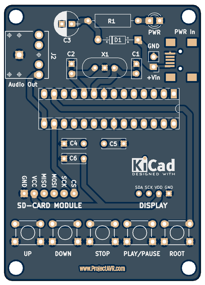
The circuit is fairly simple. An ATMEGA328 is connected via I2C to an SD1306 OLED Display and via SPI to a commonly available Micro SD Card module. Five tact switches are used for selecting the file to play and an audio output is driven directly from pin D9 of the microcontroller. The audio output seems adequate for most files but occasionally fails. I will be looking into adding a small amplifier of some sort to boost the audio a little.
The PCB was designed to be easily mounted in a box with 3.2mm holes in each corner. The display and micro-sd card module sit on the top. I have found it necessary to put a small piece of foam behind each to prevent them from bending towards the components mounted on the PCB.
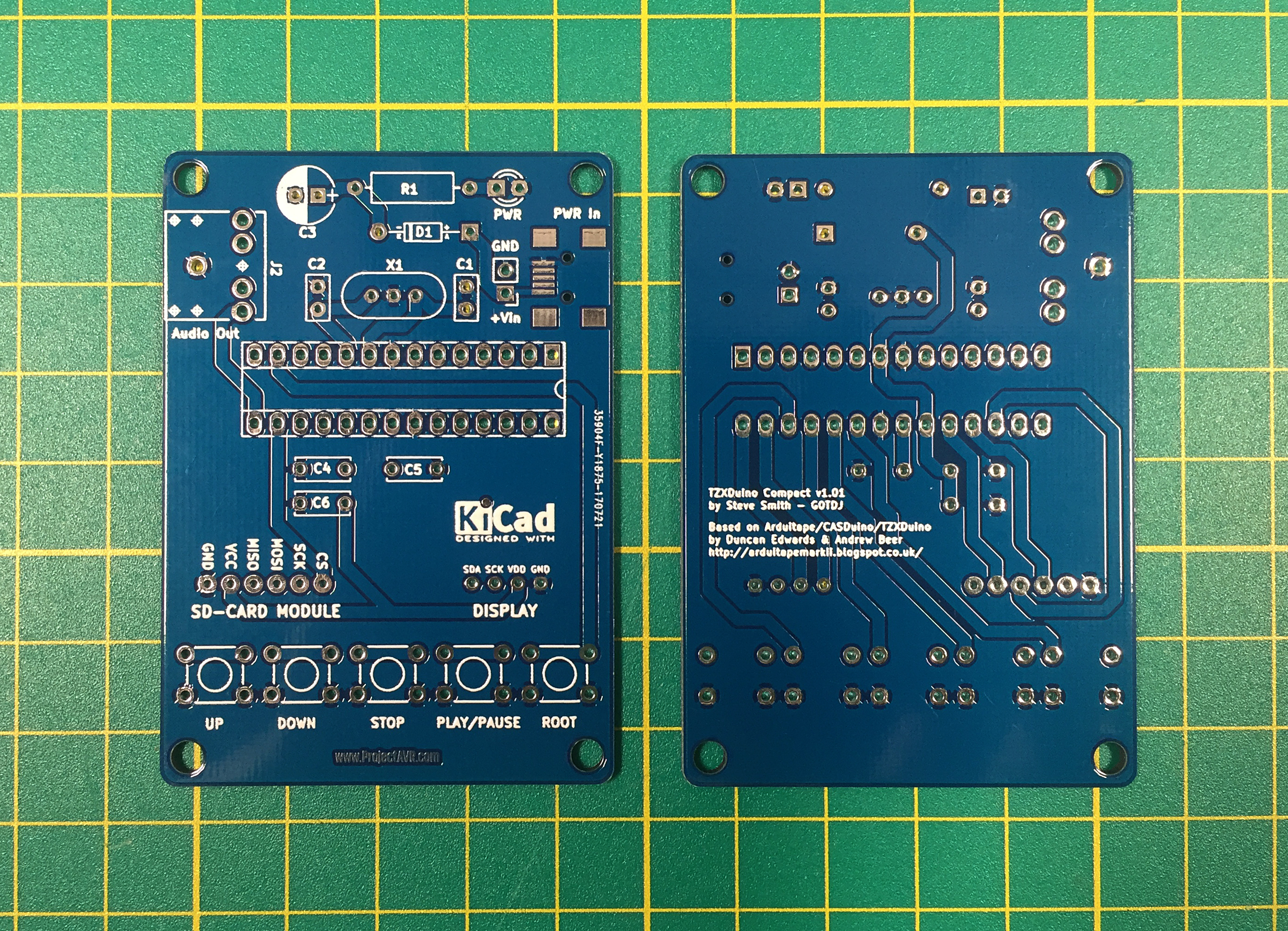
TZXDuino Compact v1.01 PCB
I had the PCB fabricated by the ever excellent Hackvana.com who always give a great service and produce really good quality boards.
As per normal with building any project, start with the low profile components first, Resistor, Diode, Crystal etc. And gradually build up to the higher components. The only difficult part to solder is the USB Mini port, in this application it is there just to supply power. You can use the two header connections directly behind the SMD pads if you prefer. The diode is for polarity protection.
The SD-Card module I purchased had a straight header already soldered on so it required de-soldering and replacing with a strip facing down, under the board. The display came without a header strip installed so it was an easy case to add one.
Programming the ATMEGA328 is made easier if you have an Arduino Uno. I extracted my Uno’s ATMEGA328 and temporarily installed a new one. I then programmed it with the ICSP header on the Uno’s board. If you have an ATMEGA328 with a bootloader, you can use the USB input as normal. If neither of these options is available, you will need to make a small adaptor board for ICSP programming, use a breadboard or perhaps, use a minDUINO as a base.
Here are all the files necessary for fabricating the TZXDuino Compact v1.01:
- TZXDuino Compact v1.01 Schematic .PDF file
- TZXDuino Compact v1.01 KiCad files
- TZXDuino Compact v1.01 Gerber .ZIP file
- TZXDuino Compact v1.01 Sketch .INO file
- TZXDuino Compact v1.01 Images .ZIP file
- TZXDuino Compact v1.01 Parts List TXT file
The entire directory of resources is available at: TZXDuino Compact v1.01
Because I used a previous version of the KiCad files, the newer v1.01 directory requires the older ‘rescue’ files. If you intend to use the KiCad files, include all the items in the zip file.
Future development may result in an amplified version of this board.
Many thanks to Duncan Edwards and Andrew Beer for designing the original.
Electronic Film Clapper v1.3
This project came about because I needed a way of marking Video and Audio files for editing. I didn’t wish to use a full size clapper for the job so I designed my own device. I chose to try the idea out on an Arduino Uno, but realising that an ATMEGA328 was a little excessive for such a trivial task, I moved over to a Digispark clone purchased on eBay. This board utilises the ATTiny85 MCU.
The requirement is to have a visual and audio que that is apparent upon editing the separate streams together. I intend to film at 25fps (Frames Per Second) so I determined that a 25ms pulse of light from an LED and an audio pip would fit into a frame. The pulse period is easily changed in firmware, as is the audio tone of the ‘pip’, although I found 4300Hz is pretty optional for my use.

ATTiny85 Clapper v1.2 Prototype
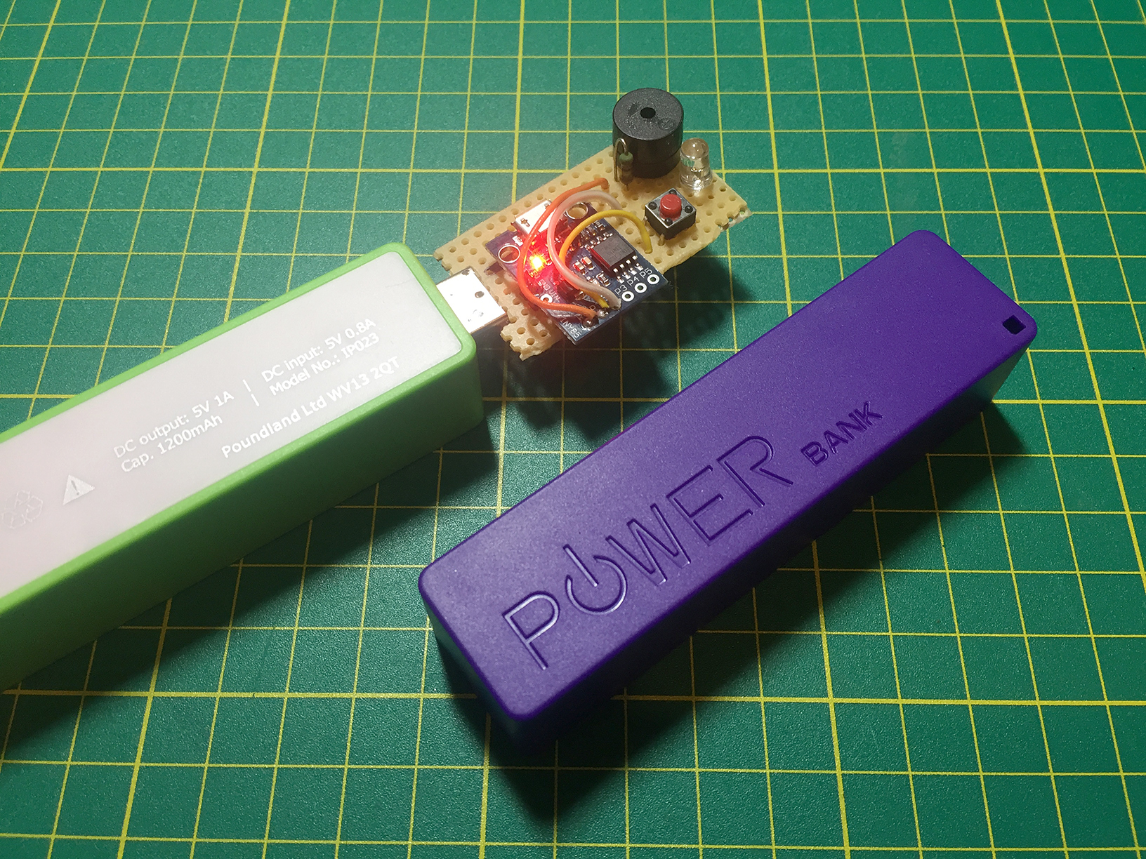
ATTiny85 Clapper v1.2 with Powerbanks
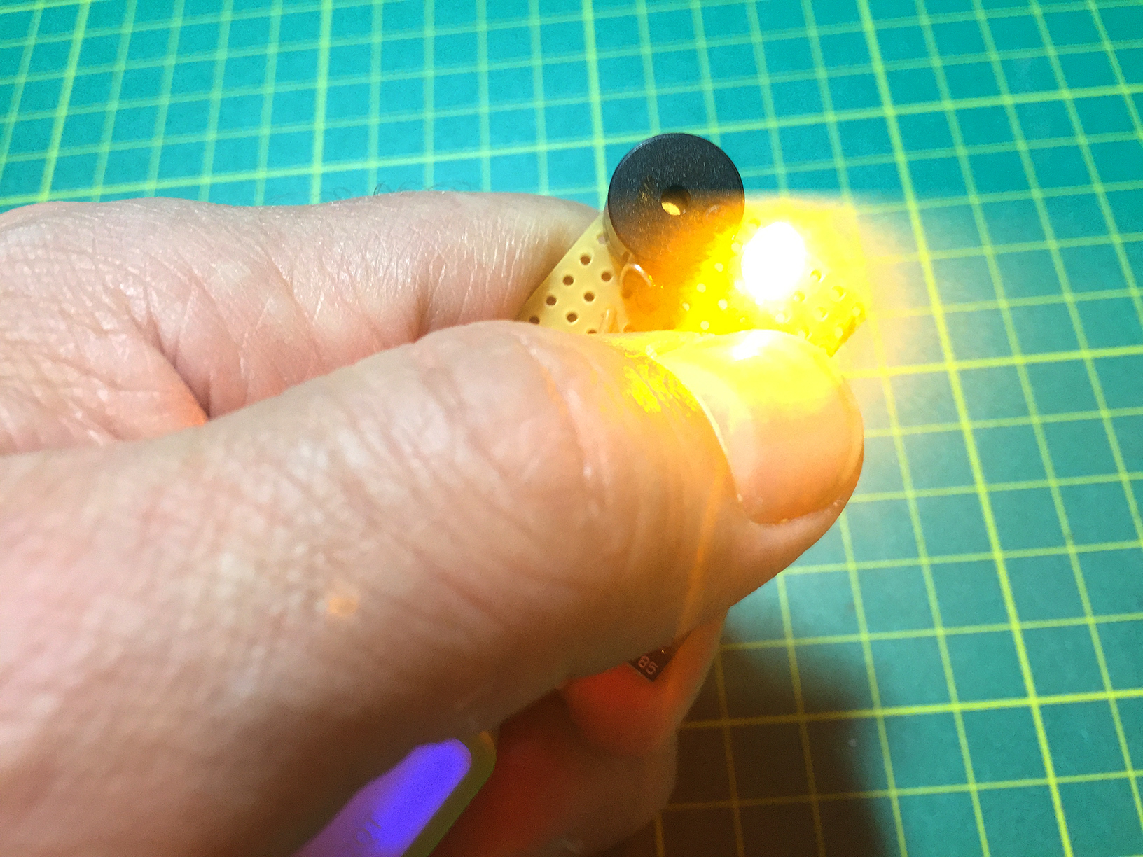
ATTiny85 Clapper v1.2 Visual Que
When the Electronic Film Clapper PCbs arrived from Hackvana.com I set about making one up. There were no issues. I remembered I’d inverted the USB plug so that the device would plug into the USB Power Bank the correct way up!
On the board, I have included several options:
- Use either a Digispark board (available on eBay and other auction sites) or a bare ATTiny85 chip.
- Use either a USB Plug type ‘A’ or feed in power via direct connections (Header compatible).
- Use either standard small tact switch or larger Omron style.
- Optionally link across R1/R3 for increased sound/visual que
The Omron switch is a little tight. The holes on the library part need to be enlarged but I have chosen to release this version none the less. A little bit of extra force sees the Omron style switch mounted. Any updates will address this issue.
Construction is straightforward. Start with the lower profile components, resistors, the polarity protection diode etc. and work up to the larger ones. I found the best way to mount the Digispark board was to use standard headers underneath and solder on the top before placing it at the appropriate place on the PCB. This creates a really secure connection. The Digispark can be programmed before or after soldering on. If a bare ATTiny is utilised, it only requires a standard 8 pin DIP socket.
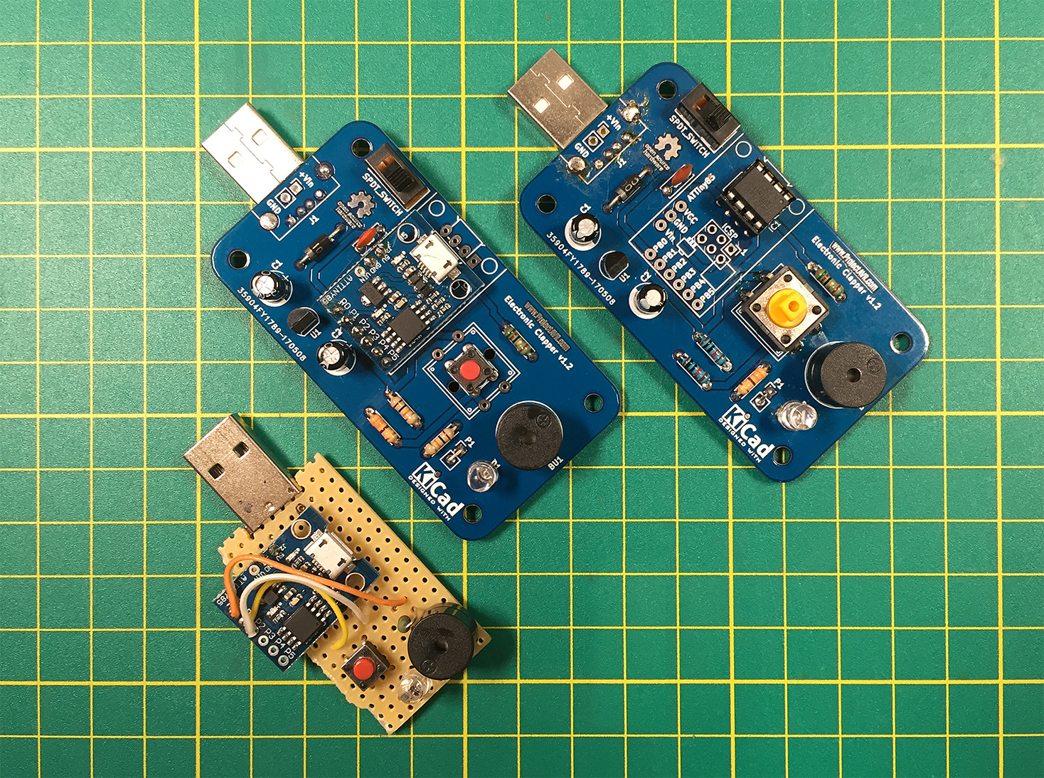
Film Clapper prototype and v1.2 boards
Programming the Digispark is fairly simple. Download the relevant files from: DigiStump Wiki and follow the instructions for installation and connection. I used the standard install to program the bare ATTiny85 via ISP but it wouldn’t work, at least, it would flash but the buzzer emitted no sound. I later (after 3 days of searching!) found out that the usual ATTiny85 libraries I had used didn’t support the ‘Tone’ function which I had used in the sketch. I managed to find this library: Arduino-Tiny on this page all about a custom tone generator library.
I built a bare ATTiny85 version to test the new PCBs, for speed and so I wouldn’t use up another Digispark board. I could also utilise the pre-programmed chip from the v1.2 prototype.
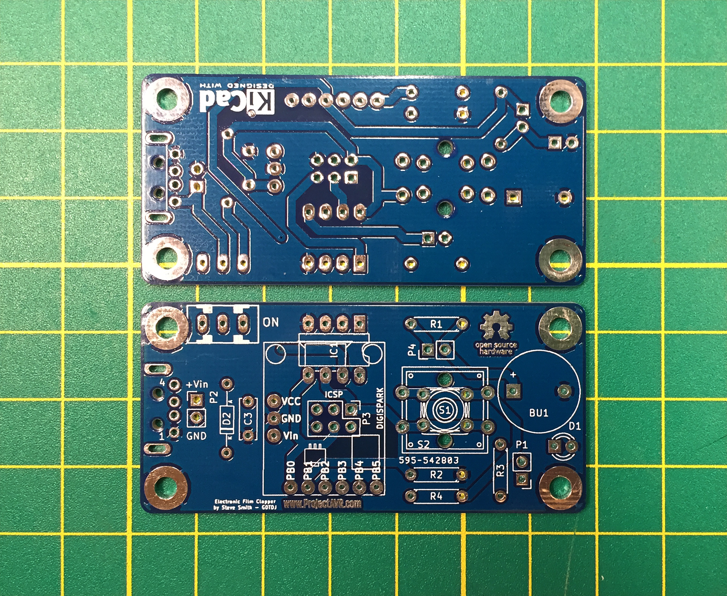
Electronic Film Clapper v1.3 PCBs Front and Back
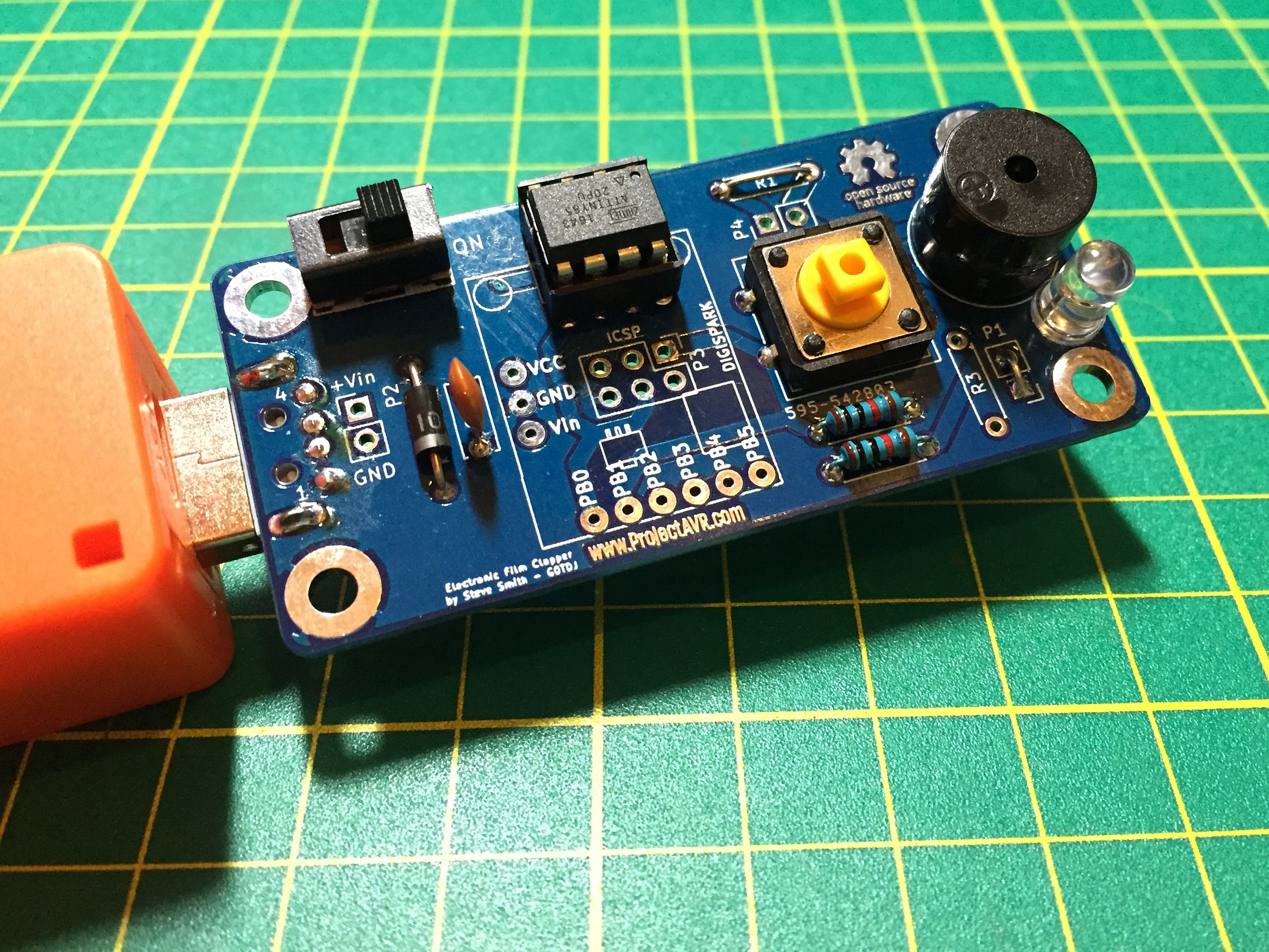
Electronic Film Clapper v1.3 mounted on Power Bank
Here are all the files necessary for fabricating the Electronic Film Clapper v1.3:
- Electronic Film Clapper v1.3 .SCH schematic file
- Electronic Film Clapper v1.3 .PCB board file
- Electronic Film Clapper v1.3 Gerber .ZIP file
- Electronic Film Clapper v1.3 Parts List — file
- Electronic Film Clapper v1.3 Schematic .PDF file
- Electronic Film Clapper v1.3 Sketch .INO file
The entire directory of resources is available at: Electronic Film Clapper v1.3
I tried using a 78L05 on v1.2 to regulate the incoming voltage, but it turned out to be too low powered and I bypassed it. In v1.3, it is completely removed. I did include the polarity protection diode in case of mistakes being made with the direct voltage input. If USB is used as a power source, there should be no issues. Remember though, the USB Type A plug sits on the reverse of the board for correct polarity.
 Electronic Film Clapper by ProjectAVR – Steve Smith G0TDJ is licensed under a Creative Commons Attribution-ShareAlike 4.0 International License. All files and information is published in the spirit of Open Hardware/Open Software
ZAViouR – Z80/AVR Hybrid board
[PLACEHOLDER]