I’ve been a licenced radio amateur since 1993. My callsign is G0TDJ. Morse was always my first love in radio although I have tried many other modes. Recently, ‘Network Radio’ was drawn to my attention by an article in a UK magazine called Practical Wireless by my friend Tim Kirby G4VXE. In the article, Tim explained the basic concept of network radio and mentioned devices that you could use. Included with these were smartphones paired with an app called Zello. I loaded up the app on my iPhone and discovered that I already had a contact. Another of my friends, Ian G7PHD. Then I remembered that Ian and I had tried out Zello a few years back and found it laclustre in performance.
It appears that Zello has now grown up as an app and works very well. At around the same time, within part of my research, I came across the ‘Network Radios‘ Facebook page. Originally, this was a single channel on Zello created by Karl G1YPQ, but has now grown to several other channels, plus a few in reserve.
It didn’t take me long to want to do some CW (Morse) on a zello channel but the devices that Zello runs on, be they smartphones or dedicated, don’t give provision for CW in any way. I sought to fix this deficiency. To this end, I designed an adaptor for my Inrico TM-7 to enable other audio sources to be fed into the microphone input. This uses the popular computer networking connector, the RJ45.
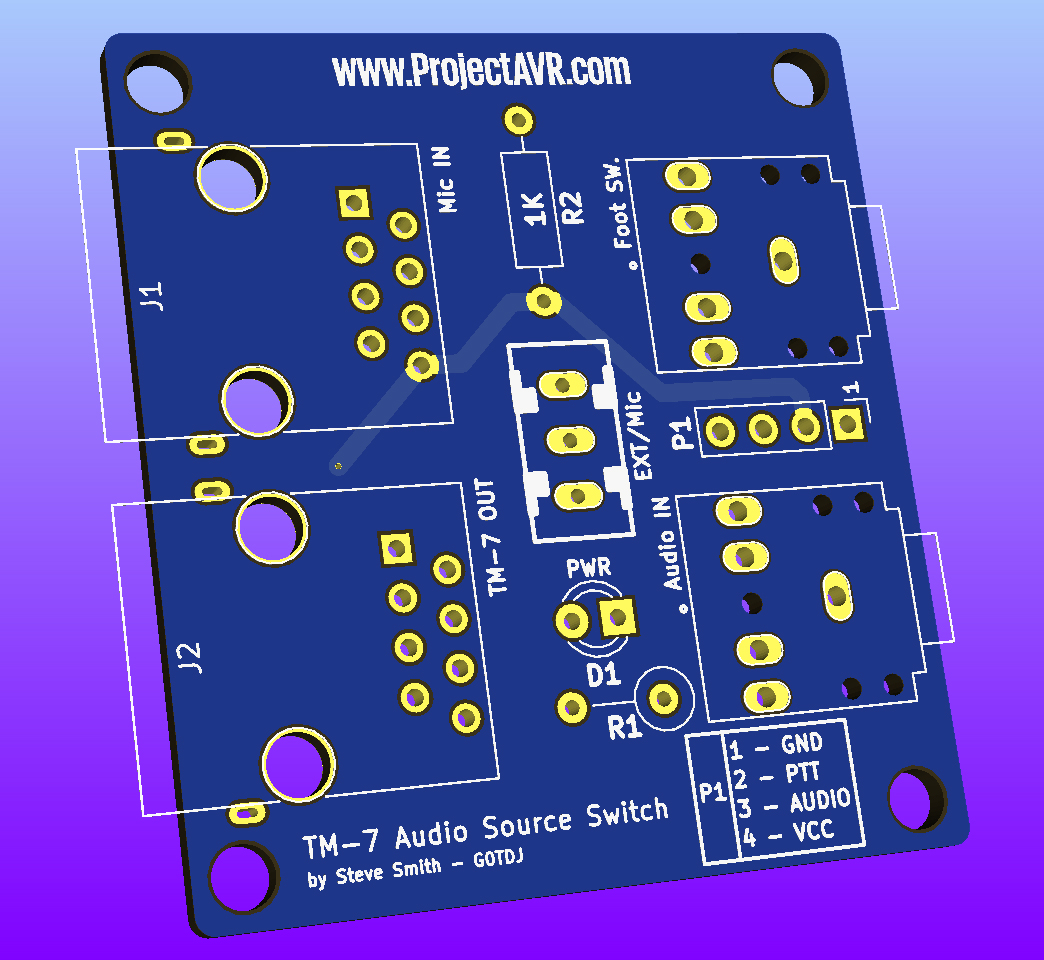
TM-7 Audio Switch v1.01
The standard microphone is fed into socket J1 and a straight through network cable is used to connect J2 to the TM-7 microphone socket. The radio can then be switched between the standard microphone or an external audio source fed into the jack socket on the back of the pcb. There is a further jack socket to provide facility for a footswitch. The pcb illustrated is the second version of the board with added screening connections on the RJ45 sockets and a breakout header for the signals. This board is currently being fabricated.
Meanwhile, I needed a method to get some Morse tones into the radio. I found a nice Twin ‘T’ oscillator on Michael Maynard K4ICY’s website. I wanted to make an oscillator that could be used for practice, as well as an audio source, so I modified Michael’s design slightly by changing the transistor amplifier to an LM386. I have published the details for this on the Non-AVR Projects page.
There is a current issue with the use of the first version of the audio switch and the oscillator. The signal is very noisy. I believe it is because the devices aren’t screened. Further testing will be done when the new boards arrive.
Another, more traditional radio, project I have been working on is a Morse Code Decoder. Although I am reasonably profficient in Morse and have many ‘normal’ contacts, I find it difficult, at least time consuming, to read callsigns in contests. The idea I had was to build a Morse decoder to catch the very fast callsigns and enable me to give more points away! I came a cross many designs online, but the one I chose to replicate I found on Hjalmar OZ1JHM‘s website. It is an ATMEGA326 with a potential divider and LED. Hjalmar provides the circuit in Fritzing style and conventional schematic and the code to drive it. I designed a PCB and modified the code to use a 2×24 line LCD display.

CW Decoder v1.01
I had a few issues with the first PCB I had fabricated. For some reason, I had put the LCD pins in the wrong place for a straight through ribbon connector. I obviously didn’t check the design enough before I sent it. Coupled with this, on the first PCB I built, there was a problem with the clock oscillator. I attempted to fix this but the tracks on the PCB started to lift. I cut my losses and built a new one. This one, as you can see in the image above, worked fine. The newer version of the board, yet to be fabricated, includes the display pins wired correctly.