ProjectAVR now has a Twitter account. The truth is that it was getting a little confusing tweeting from the Project_HAB account about Project_AVR stuff. It needed to have it’s own account for organisation sake. Hopefully now, tweets from both accounts will make more sense.
To Tweet Too Who
Summer Developments
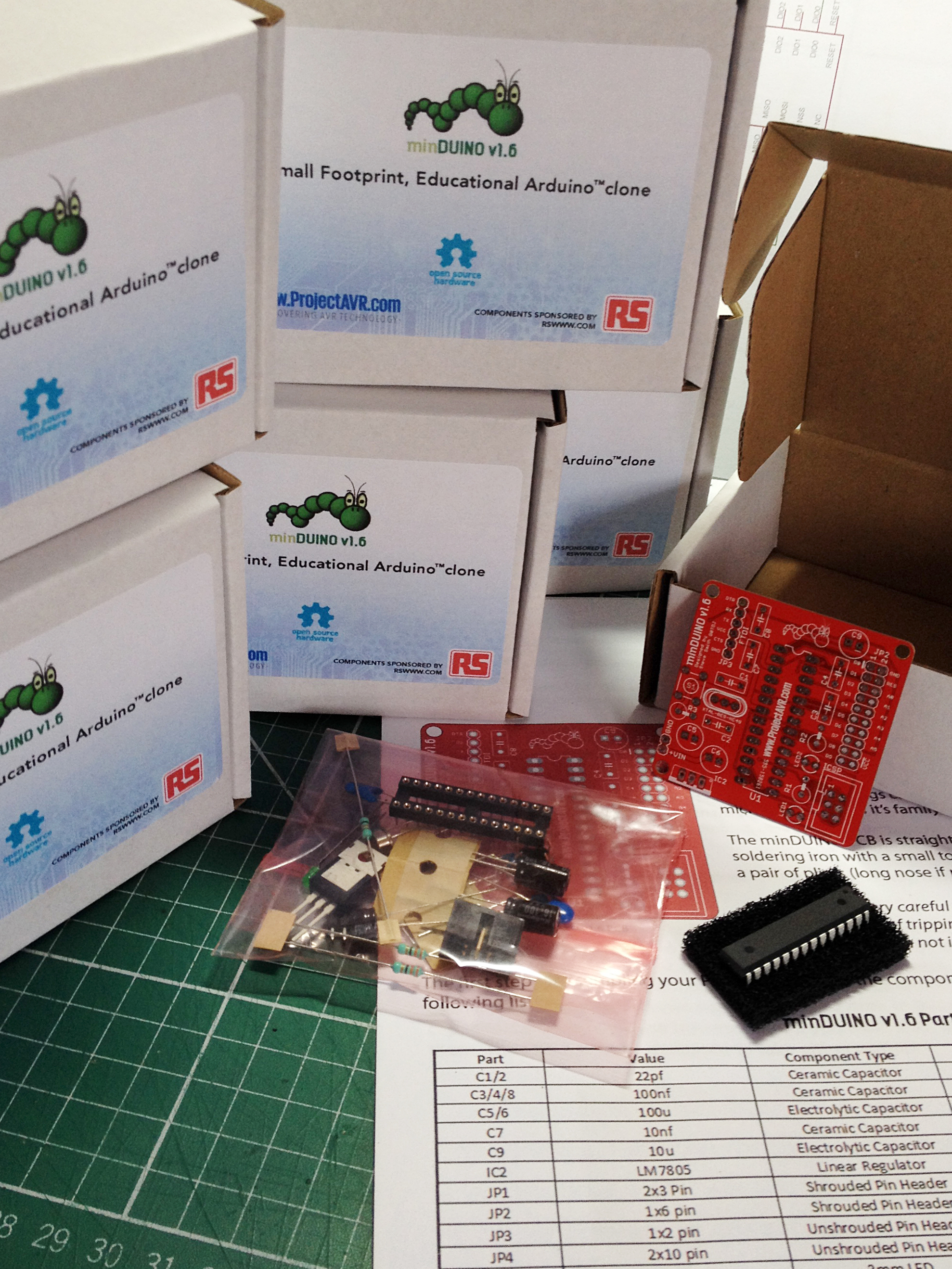
It’s been busy at ProjectAVR. I’ve been squirreling away, making up minDUINO kits for the Scouts JOTA event. They are almost finished now. Just a few last minute additions on back-order. The assembly instructions are complete with included circuit diagram and components key.
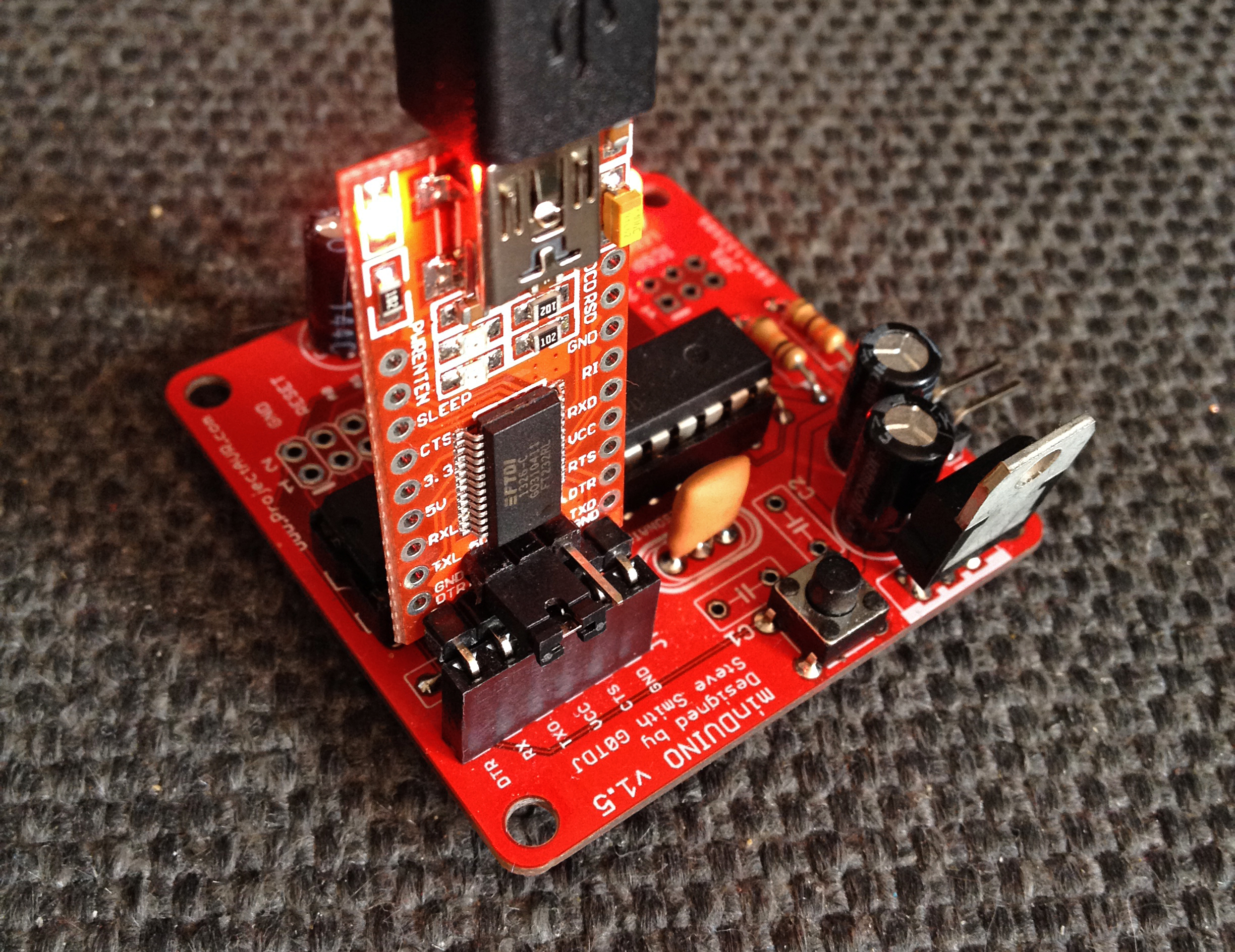
I managed to find the perfect sized boxes on eBay and print up some natty labels. I wanted to give the impression they were commercial kits.
A special mention has to go to RS Components who have shown outstanding generosity in not only sponsoring the components for the minDUINO kits, but also in supplying five soldering kits for the Scouts to use. These will be invaluable for building the kits but also for their ongoing education in electronics.
Meanwhile, ProjectHAB (still me!) has been working on a High Altitude Balloon payload to demonstrate to the Scouts for their JOTA event on October 19th. Hopefully the conditions will be right for a launch and tracking. I’m going to attempt to get the balloon to ‘Float’. This is when the ascent is slow enough not to rupture the balloon and maintain a steady altitude once it reaches a point of buoyancy. I’ll make an announcement for the launch closer to the time on this blog and on the UKHAS Google Group.
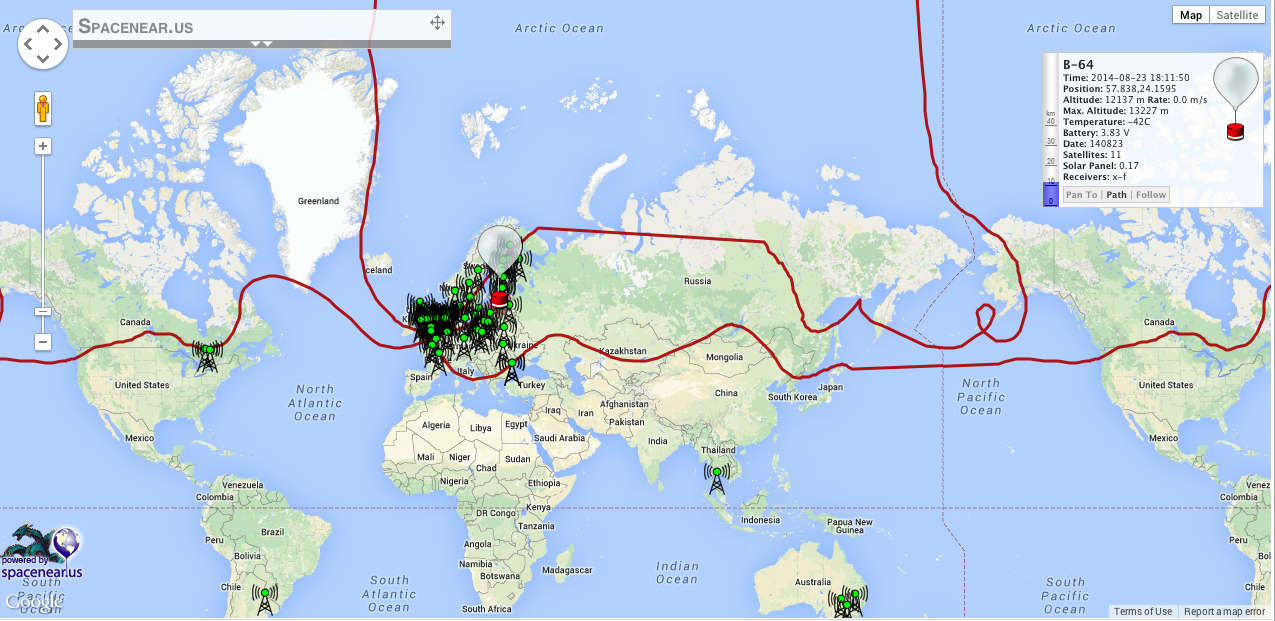
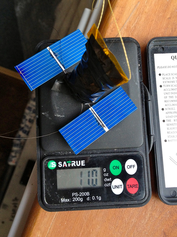
Several amazing achievements have been made in HAB (High Altitude Ballooning) recently. One HAB enthusiast, Leo Bodnar, has circumnavigated the globe with two different balloons, what’s more, they both orbited twice! Leo uses a clever combination of solar powered tracker modules and his own home-made envelopes (balloons) to do this.
Although I don’t expect to circumnavigate the globe with my Scout demonstration, I would like to get into a float and perhaps, be tracked into near Europe.
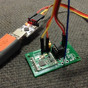
Another project I have become interested in is UKHASNet. This is an amateur sensor network. It is hoped to use the technology for tracking balloons too so it makes a nice crossover point. I have built two ‘nodes’ so far. One is a gateway and is connected to my main PC. It also samples temperature and sends that information into the system, as well as listening and repeating any other nodes it ‘hears’.
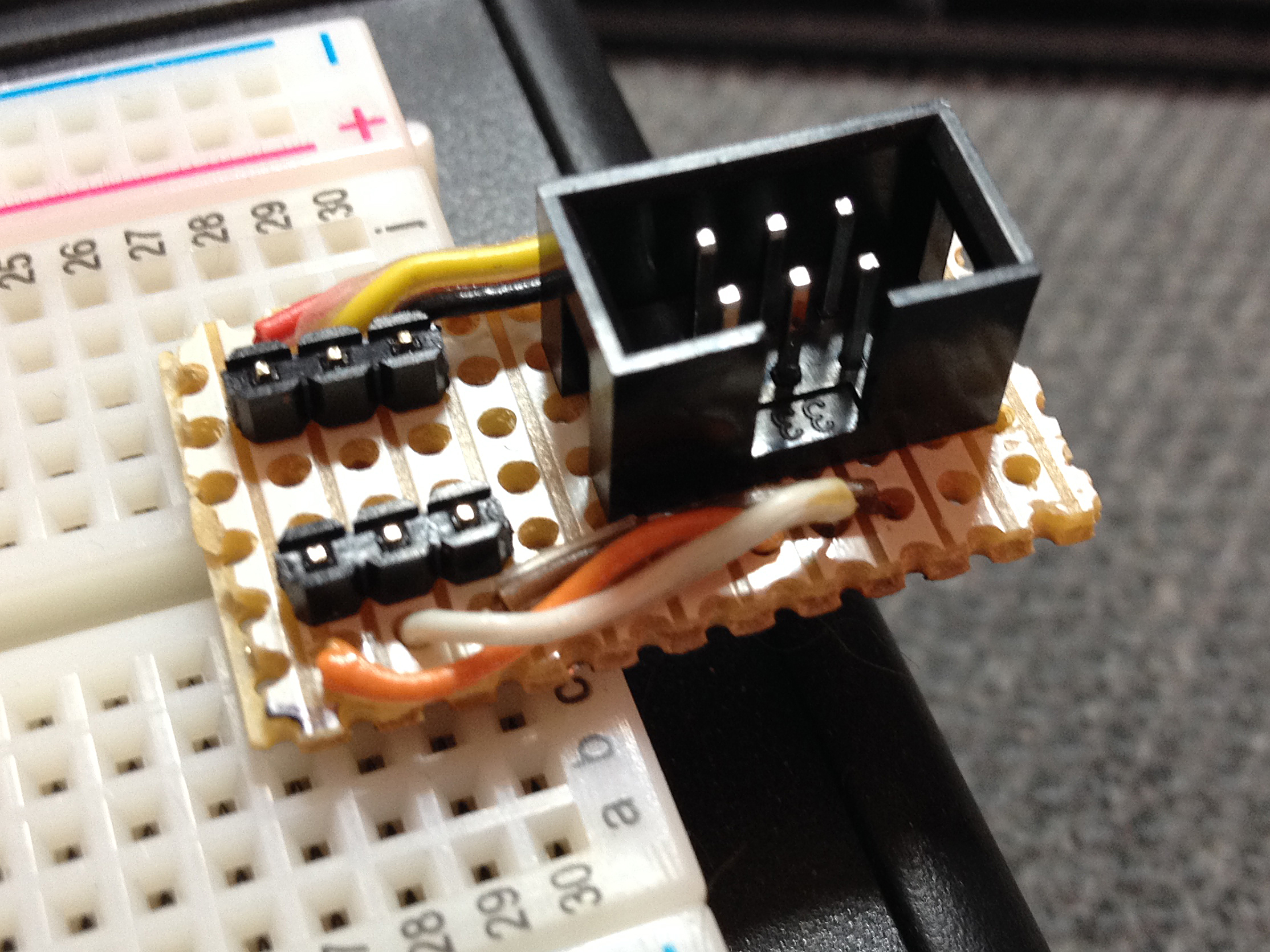
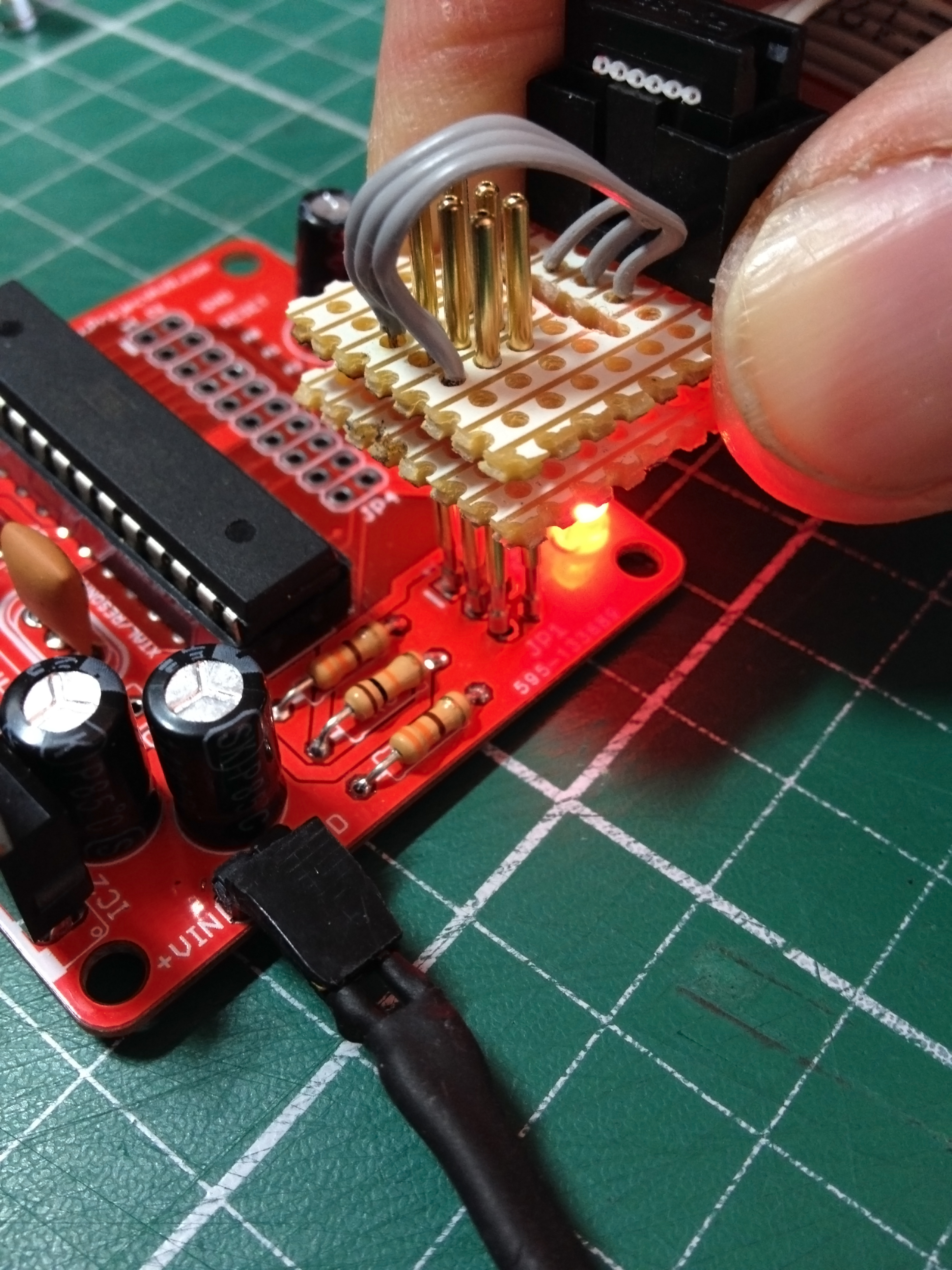
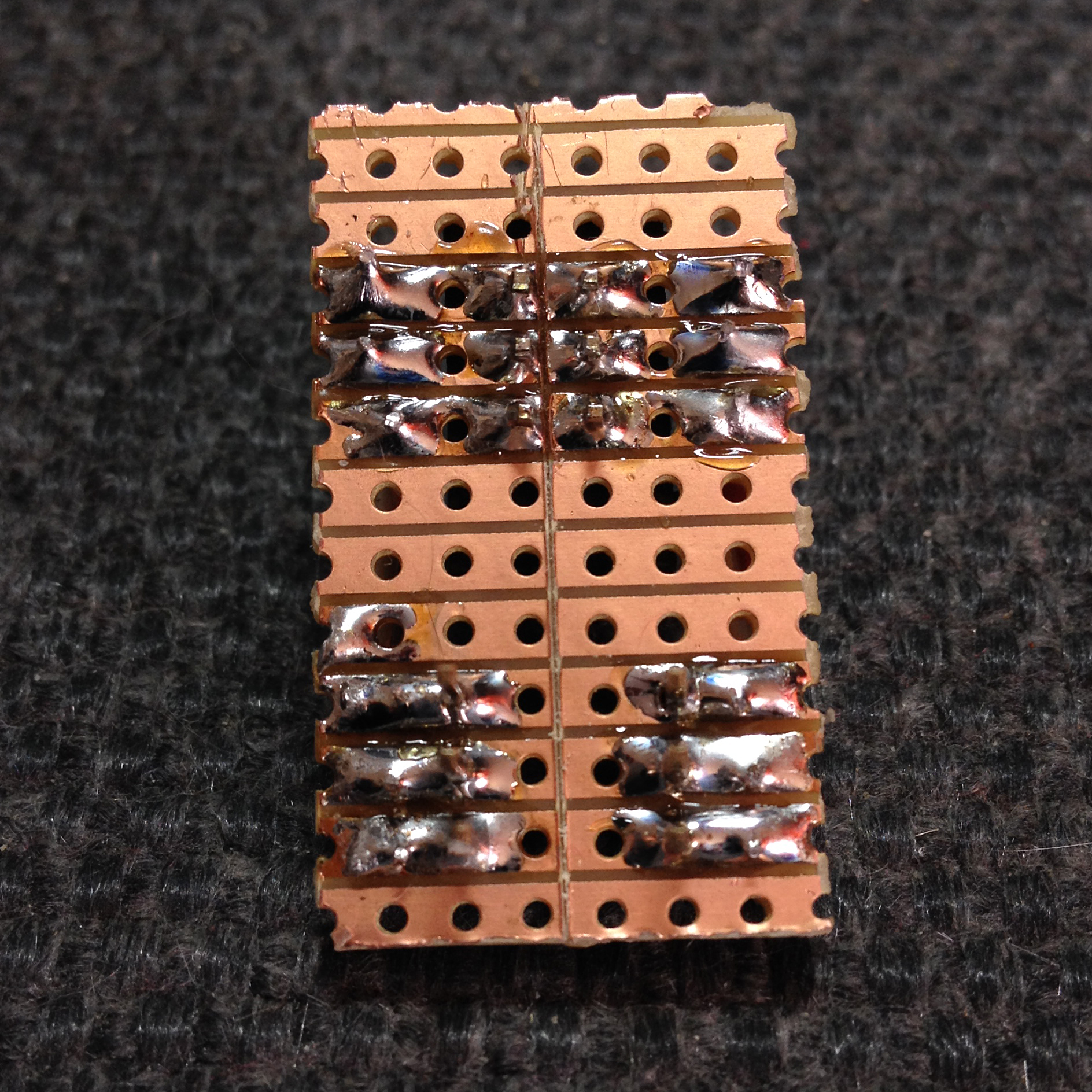
CFORD1, my first node, is based upon an 8-pin LPC810 programmable microcontroller and was designed by James Coxon. The firmware samples the temperature from the RFM69HW transmitter module and together with some other telemetry, it sends that via a serial link to the CR2012 module which converts the serial information to USB. This in turn is received by a Python script running in PythonWIN and then sent to the UKHASNet server.
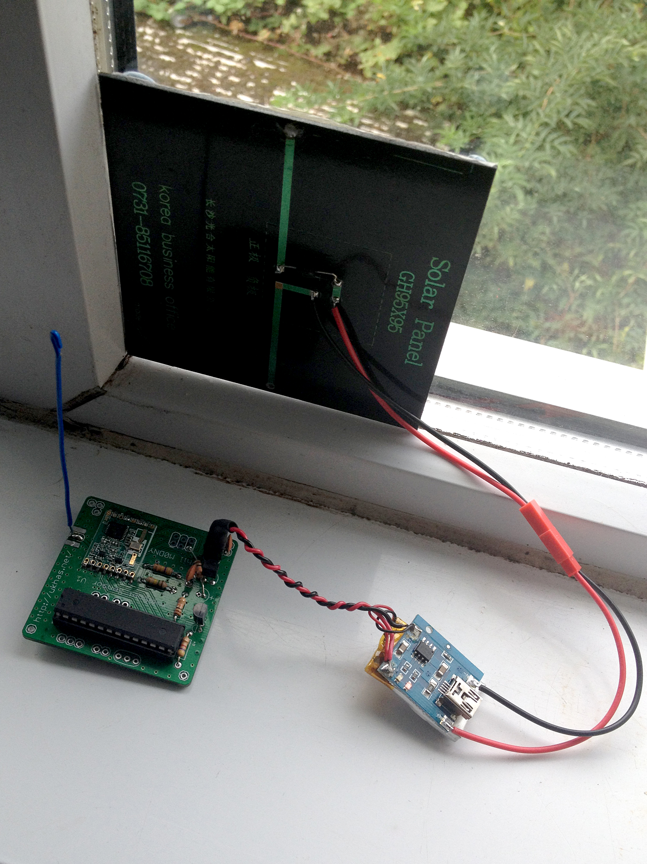
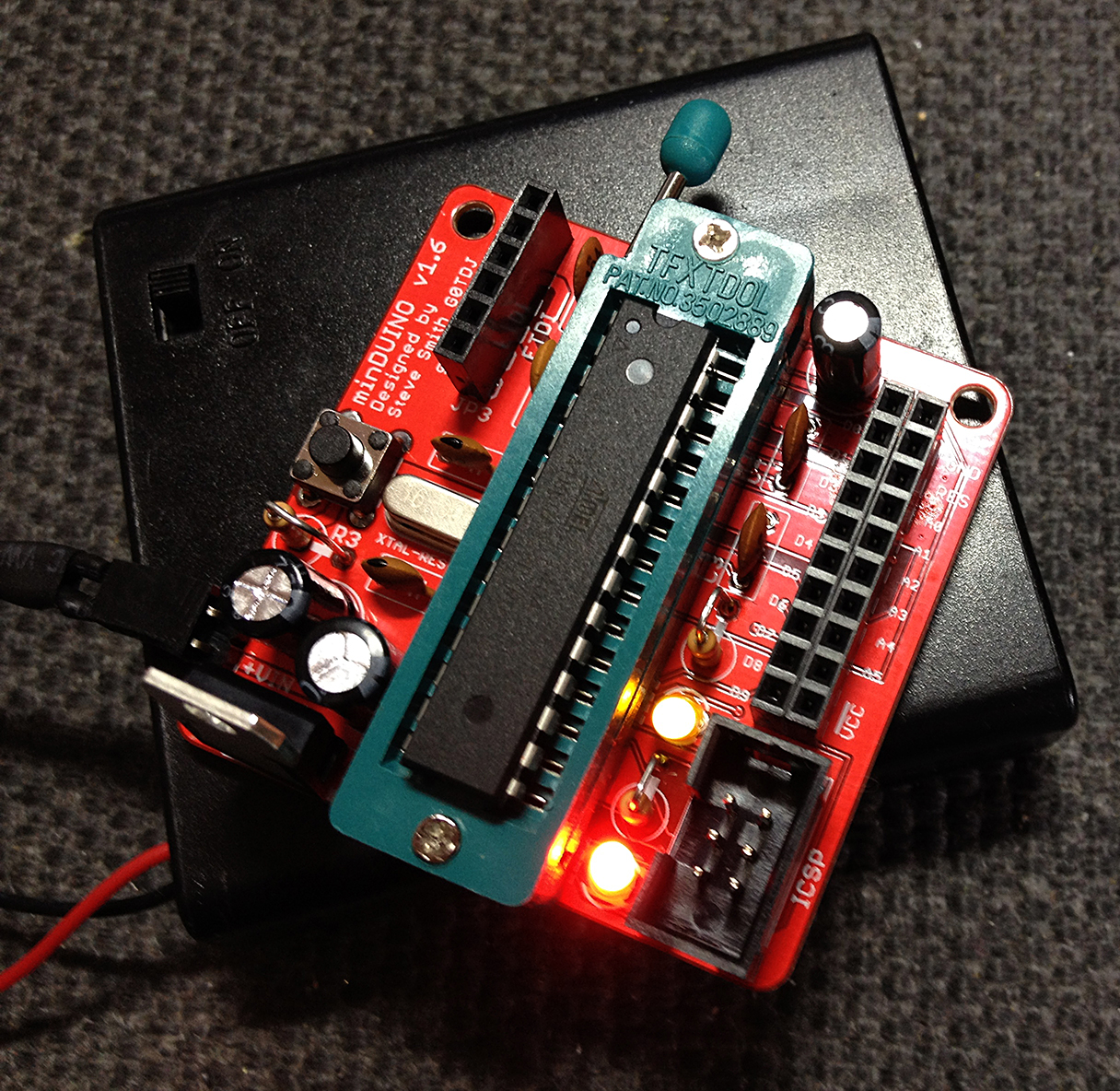
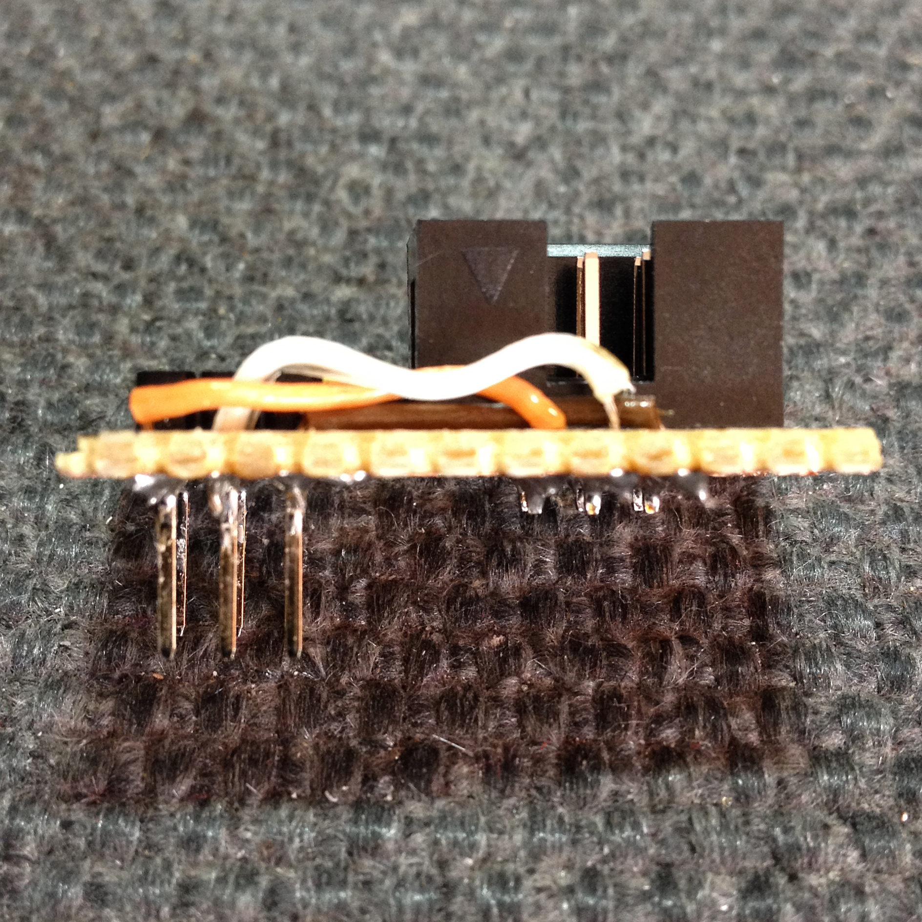
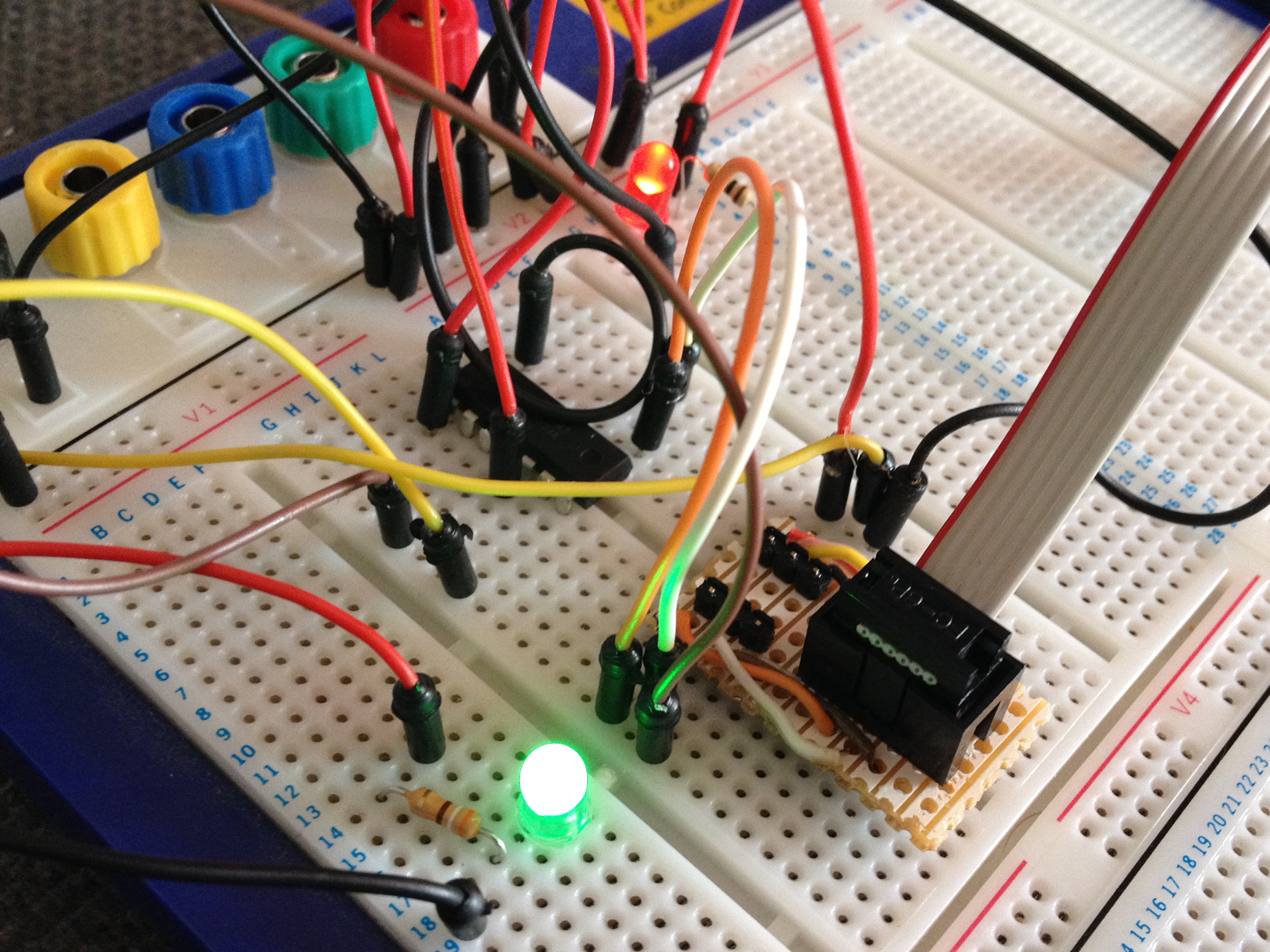
My second node, CFORD2 designed by Phil Crump, is an ATMEGA328 based design which I’m more at home with (although the LPC180 was a breeze to program). I have made CFORD2 autonomous by providing a Lithium Polymer rechargeable battery fed with solar power from a panel affixed to a window as suggested by Phil.
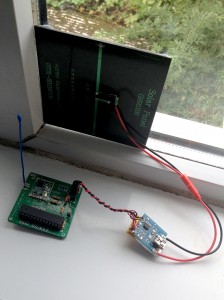
This node, in common with CFORD1, samples temperature but also the voltage of the battery input to the node. Currently, both nodes are not calibrated so the readings may be very inaccurate but the interesting thing to observe is the trends and how they repeat day after day.
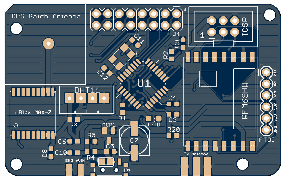
Just like the HAB Tracker CHEAPO, I decided to develop Phil’s circuit a little and add a breakout for the ATMEGA328 pins, a dedicated Temperature/Humidity sensor and include a GPS to avoid having to hard-code the Lat/Lon co-ordinates. I also chose to make the PCB in SMD to keep the boards small. I will be getting these PCBs fabricated in the near future.
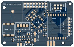
Phil’s firmware should run on this board with no change since it is much the same circuit that he designed. It just has a few extras which I will add code for at a later date. I have also designed a daughter board for minDUINO v1.6 boards to expand them into sensor nodes with a simple add-on.
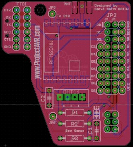
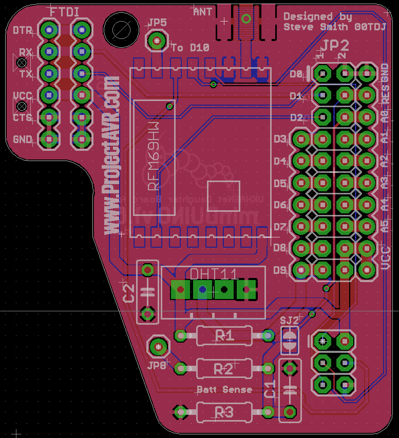
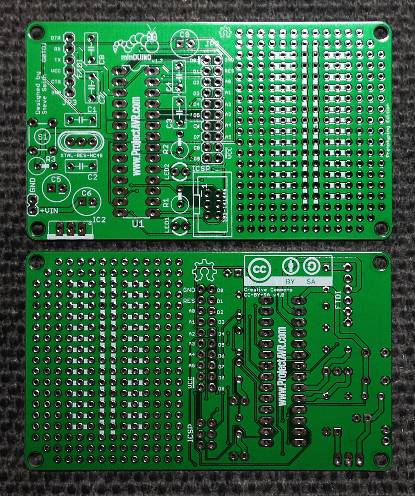
Again, these are based on Phil’s circuit but the daughter board has no GPS on board. I will decide whether to get these fabricated after testing the full GPS Sensor node PCBs. At this point, I will also publish all the design files for the GPS Sensor Node.
JOTA – 2014
This year, I’ve been invited to the Scouts JOTA/JOTI event on October 18 & 19th. JOTA (Jamboree on the Air) & JOTI (Jamboree on the Internet) organises Scouts all over the world to communicate via radio and the internet.
Primarily, I was invited to launch a High Altitude Balloon for the Scouts to track and receive telemetry but I suggested that it might also be a good idea to get the Scouts to assemble a minDUINO to take home with them to aid their education in electronic engineering. It will also give them an introduction into microcontrollers and how they are programmed. I decided the minDUINO v1.6 was the best board to make a kit out of since it can be used as a general board, a programming board or for prototyping, with an inexpensive additional breadboard.
Making fifty kits of parts is a fairly costly proposition so I looked for a likely sponsor. The company I chose was RS Components. This is a very well established organisation, renowned for it’s quality products and first class customer service. I was extremely pleased to get a swift reply to my initial inquiry:
“We are always interested in supporting the Engineers of the future, especially in promoting an interest on Electronics. The Jamboree sounds very interesting and is something that we could possibly help with.”
I have since supplied RS Components with a full list of parts for the minDUINO v1.6 and they have them on order. I have also ordered the PCBs which are being fabricated by Hackvana as I type this article.
I am very much looking forward to making the kits up and especially looking forward to assisting the Scouts in building their minDUINOs. This is the sort of opportunity I would have relished as a young lad myself and I’m very happy to be contributing to the countries up and coming engineer base.
ICSP to Breadboard Adaptor
Frustrated by having to poke jumper wires into the socket of my AVR ISP MkII every time I wanted to program a breadboarded AVR, I quickly built an adaptor from strip board. It consists of a 6-pin shrouded header plug and two lines of three header pins.
Construction is fairly straightforward as you would imagine. First cut a piece of strip board 12 lines by 8 columns, or thereabouts. Make a cut straight down the center.
OK, mine isn’t quite central but you get the idea. Check the cut under a magnifying glass, I have found that this is useful to see any swarf that is creating a short-circuit. You can test the breaks with a multi-meter set to Ohms or Continuity if you like.
Prepare the header pins by pressing down on the plastic to the short end to reveal as much of the pins as possible. I do this with needle nosed pliers. Then feed them through the strip board two holes away from the cut to suit breadboard’s center channel. Solder them in. I tend to solder one pin and then straighten by touching the reverse side and reheating the first connection. Careful not to burn yourself on the heated pin and do this very quickly to avoid the header strip melting.
Solder in the shrouded header plug a few holes away from the header pins and straddling the cut. Once it is in place you can solder wires across from the shrouded plug to the header pins. I have developed my own colour code to aid me when connecting up but feel free to use your own. I found a piece of scrap ribbon cable to source my connections from. The colours I use are:
- Red – VCC
- Yellow – MOSI
- Black – GND
- Orange – MISO
- White – SCK
- Brown – RESET
Once you have soldered these connections, double check your soldering with a magnifying glass or multi-meter, just to be sure. Bridging connections is very easy on strip board, something I’ve found out to my cost!
To use the device, find a spare area on your breadboard and place the adaptor so the header pins straddle a channel, just like a DIP Chip would. Press in firmly and then you can connect the programming lines to your project with jumper cables without damaging the programmers connector.
minDUINO v1.7 Arrival
I’m very pleased to report that the minDUINO v1.7 boards have arrived and are excellent! Fabricated by the fantastic Hackvana. They have never failed to deliver a top quality product.
I’m very much looking forward to building one up to prove all is OK and then I will post the design files on the minDUINO page. The main feature of this board is the prototyping area which I added to facilitate experimentation. I have emulated the style of many prototyping boards in that I have included two central rails for power or signal and sets of three points for adding components across chip pins.
I’m hoping that between versions 1.5, 1.6 and 1.7 there will be a minDUINO to fit many criteria for experimenting and learning about AVRs.
[UPDATE]
I have now assembled a test board and it checks out. I have posted all the necessary design files on the minDUINO Page.
minDUINO ‘Hello World’
This post assumes that your ATMEGA328 chip has a bootloader installed. Chips with the bootloader already installed can be obtained from many sources, including eBay. Details on how to install a bootloader manually will be detailed in a future post.
So, you’ve built your minDUINO and you need to test it. What do you do. The easiest way to test it is to get a real program running. Traditionally it’s a blinkenlight (Flashing LED). This is why a regular Arduino™ board has an LED on digital pin 13. However, I deliberately designed the minDUINO to have an LED on digital pin 10 which is a PWM pin and therefore I could demonstrate PWM to Amelia (who the board was originally designed for).
To run the test, connect your FTDI module to the minDUINO’s FTDI header, If you have the right module you can plug it directly in, otherwise, you can use easily obtainable flying leads.
You will see that the board is powered through the FTDI adaptor. Don’t attempt to power it externally at the same time.
Load the Arduino IDE and go to File-Examples-01.Basics-Fade Clicking on this loads another instance of the IDE. You may close the first one if you like. In the code, you will notice the pin designated is pin 9.
int led = 9; // the pin that the LED is attached to
Edit this to read ‘int led = 10;’ since our LED is on Digital Pin 10. Leave all the other code alone for now and click the tick icon to check it compiles. If not, check you haven’t changed anything else in the code and if necessary, start again.
Once the code compiles correctly, click the upload icon and the compiled code should upload through the FTDI module to the minDUINO and hopefully you will be greeted by an LED fading up and down in brightness. If this doesn’t happen, double check you have connected the FTDI module correctly, paying particular attention to the TX and RX lines. The header pins should match the FTDI module and not be swapped.
If this proves not to be the problem, double check that you have soldered the LED/s in the right way round. It is very easy to get this incorrect.
Hopefully, this will give you a quick and easy way of proving if your minDUINO is alive and well and lead to further experimentation.
ICSP Test Rig
On a whim, I bought a Maplin project to build. I needed an audio signal generator for something I’m planning and the £15.99 Function Generator Kit seemed to fit the bill. I have a very local Maplin shop where the staff know me by name and I was passing by today so I picked one up. This particular board attracted me because it utilises an ATTINY2313 chip as a generator along with a resistor lattice.
It took around 45mins of careful construction after which I had a very functional Audio Signal Generator.
I did wonder though; Had the ATTINY’s lock fuses been set? AVRs have special fuses in them which allow the programmer to ‘Lock’ the chip after programming, preventing anyone from reading the code. The Function Generator PCB didn’t have any provision for ICSP (In Circuit Serial Programming) so I had a look around the workshop to see if I could make a testing jig. Something that would be useful in the future. I settled on a small, inexpensive prototyping PCB I had bought. I mounted sockets for 28-pin and 8-pin chip variants and a set of headers along each side to access the chips pins. I then soldered sets of three connector headers above and below to act as power rails. I also bridged the power rails into the prototype boards inner rails so the power would be available at both ends of the board.
Once I had checked all the solder joints, I mounted the ATTINY from the Signal Generator on the test board and connected the relevant pins up by checking the datasheet. I had already made a back-to-back ICSP adaptor to use flying leads with my AVR ISP MkII. This allows connection via flying leads rather than the 6-pin ICSP connector provided by the programmer.
I connected the flying leads to the AVR ISP MkII via the back-to-back adaptor and fired up the jigs power. I plugged the AVR ISP MkII into the USB port of my PC and I was pleased to see a green light indicating that all was well.
I then loaded AVR studio and connected to the programmer. I was astounded to find that the lock fuses had not been set and that I could freely do a dump of the Flash area! I checked the EEPROM area too but there is no data there. I have kept a ‘backup’ of the flash to study and in case I need to program a replacement chip.
ICSP Pogo Pin Programming Adaptor
Driven by my frustration at not being able to find a reasonably cheap supply of 2x3pin shrouded header sockets, I have knocked up an adaptor to avoid using them altogether. This is not a new idea and I’ve seen a few variations online before. However, I wanted to make one with the materials I had available. I don’t like stripboard much but I have a supply of it to use up so I decided that was the way to go. The theory of making it is quite easy, the practice is something else. I believe this is the most fiddly project I’ve ever undertaken.
The design I came up with requires two pieces of stripboard, each with 12×7 holes available. On the top layer goes (from left to right) a 6-pin male header with all the pins pressed down as far as they will go. A shrouded 6-pin header socket. Three short hook up wires and six 1.36mm Pogo Pins (I sourced these from eBay).
To prepare the header, use a pair of pliers to press down the black plastic against a firm surface. I used my workbench.
Next, make the relevant cuts in the stripboard. Remember to make a cut between the pins of the shrouded socket. Three cuts in total on the top layer and one on the bottom layer between the Pogo Pin positions. Also be aware that my illustration is looking from above.
You will then need to drill out the six Pogo Pin holes to 1.36mm. The standard strip board holes aren’t large enough. I used a small Dremel-like drill in a small drill press to accomplish this. The holes need to be absolutely vertical otherwise it will cause registration issues later on with the pins. Finding it very difficult to measure the drill bits I have, I did a few test holes on a gaff piece of stripboard to ascertain the correct bit for the job.
Once you have done these steps, you can proceed with the assembly. Brace yourself, it’s a really difficult process! Not kidding.
The first thing I did was to solder the 6-pin spacing header, the one you pressed the plastic down on. Then solder the shrouded header socket. Now the fun begins; Because the Pogo Pins will only go through the enlarged holes one way, you need to feed both boards onto them at the same time from the back. But you still have to leave enough room for soldering the top layer. I managed to get the bottom layer to stay above the copper coloured part of the Pogo Pins to give me enough room…eventually. I set the inverted board down on a level surface and used the shrouded header socket to keep it so. All Pogo Pins should align at roughly the same place. This is important so don’t rush it. You may need to encourage one or two of the pins to get them all aligned properly.
Very carefully solder the Pogo Pins taking care not to bridge across either your cuts or between the tracks (I managed to do both!). It’s worth mentioning I used the thinnest soldering iron bit I could whilst doing this.
Once you have successfully soldered the pins, you need to solder three small hook-up wires between the shrouded header connections and the far end Pogo Pins. The first diagram indicates this. By the way, can you spot the obvious mistake in the above image? Answer later on…
Once you have got this far, you can feed the board down the Pogo Pins and align it with the back pins on the header. This header helps to align the two pieces of stripboard correctly. Be careful not to stress the Pogo Pins at this stage. Again, take your time. Once you have fed the board down, you can solder both the header pins and the Pogo Pins.
Hopefully your adaptor will now look like this without the rather obvious drilling between the hook up wires and the Pogo Pins. This was the mistake I alluded to earlier. I’d forgotten one of the cuts. After assembly, the only way I could break the connections was to drill them out. A lesson learned!
Still, after all the trials of making it, the adaptor does work and it will save me a bundle in 6-pin shrouded header sockets. I just don’t want to have to build another!
Last of the line?
Having now designed and proved the minDUINO v1.6 board, I’m intending to mount one on a box with a breadboard for rapid prototyping. However, it struck me that it wouldn’t be too difficult to add either a daughter board that would sit on the GPIO header (like the VAYU_NTX Expansion boards) or to add a prototyping area to the board. I elected to add a prototyping area and the result is this:
I based the prototyping area on several boards I have seen sold commercially and also added the newly created minDUINO logo and the ProjectAVR wordmark. The silkscreening for the prototype rails and connections is copied on the back of the board where the Creative Commons BY-SA and Open Hardware logos reside.
I have ordered the boards from my favorite fabrication house, Hackvana and as soon as they have arrived and I have double-checked they are OK, I will publish the design files on the minDUINO page.
This should be the last in the line of the minDUINO designs. It’s been fun getting all the details correct, making a couple of mistakes and seeing the final products working. I believe, between version 1.5, 1.6 and now v1.7, there’s a minDUINO to fit a multitude of uses. I’d now like to focus on the HAB tracker I have been designing, the VAYU-NTX. Design files are on my other website ProjectHAB.
minDUINO gets a logo
One of the other strings to my bow is Graphic Design. I’m self taught and have been dipping in and out of the graphic water for many years. I have designed lots of logos for various entities in the past and as the minDUINO is evolving into a nice package, I thought I’d have a go at designing it a logo of it’s own.
I had a good think about what I meant to accomplish with the minDUINO boards. An easy step from either a true Arduino™ board or a breadboarded variant. Or a platform for experimentation or learning about micro-controllers. I wanted a children friendly image, something that younger people could relate to. And then the inspiration came! There is an insect that has the right kind of image and transforms into something different as it’s life cycle progresses. A caterpillar!
I drew the caterpillar’s segments in the shape of an ‘M’ and added a few facial details to anthropomorphise it a little (make it human like). I’ve created an Eagle Cad version in black & white to add to the boards later.