Driven by my frustration at not being able to find a reasonably cheap supply of 2x3pin shrouded header sockets, I have knocked up an adaptor to avoid using them altogether. This is not a new idea and I’ve seen a few variations online before. However, I wanted to make one with the materials I had available. I don’t like stripboard much but I have a supply of it to use up so I decided that was the way to go. The theory of making it is quite easy, the practice is something else. I believe this is the most fiddly project I’ve ever undertaken.
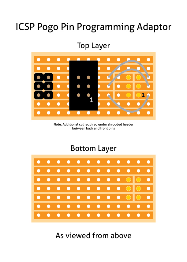
ICSP Pogo Pin Programming Adaptor
The design I came up with requires two pieces of stripboard, each with 12×7 holes available. On the top layer goes (from left to right) a 6-pin male header with all the pins pressed down as far as they will go. A shrouded 6-pin header socket. Three short hook up wires and six 1.36mm Pogo Pins (I sourced these from eBay).
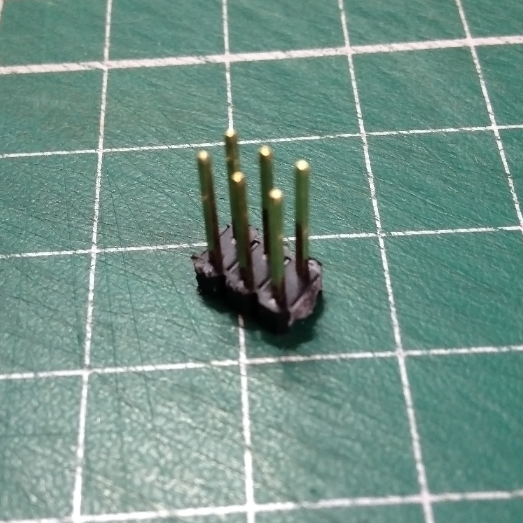
Header Preparation
To prepare the header, use a pair of pliers to press down the black plastic against a firm surface. I used my workbench.
Next, make the relevant cuts in the stripboard. Remember to make a cut between the pins of the shrouded socket. Three cuts in total on the top layer and one on the bottom layer between the Pogo Pin positions. Also be aware that my illustration is looking from above.
You will then need to drill out the six Pogo Pin holes to 1.36mm. The standard strip board holes aren’t large enough. I used a small Dremel-like drill in a small drill press to accomplish this. The holes need to be absolutely vertical otherwise it will cause registration issues later on with the pins. Finding it very difficult to measure the drill bits I have, I did a few test holes on a gaff piece of stripboard to ascertain the correct bit for the job.
Once you have done these steps, you can proceed with the assembly. Brace yourself, it’s a really difficult process! Not kidding.
The first thing I did was to solder the 6-pin spacing header, the one you pressed the plastic down on. Then solder the shrouded header socket. Now the fun begins; Because the Pogo Pins will only go through the enlarged holes one way, you need to feed both boards onto them at the same time from the back. But you still have to leave enough room for soldering the top layer. I managed to get the bottom layer to stay above the copper coloured part of the Pogo Pins to give me enough room…eventually. I set the inverted board down on a level surface and used the shrouded header socket to keep it so. All Pogo Pins should align at roughly the same place. This is important so don’t rush it. You may need to encourage one or two of the pins to get them all aligned properly.
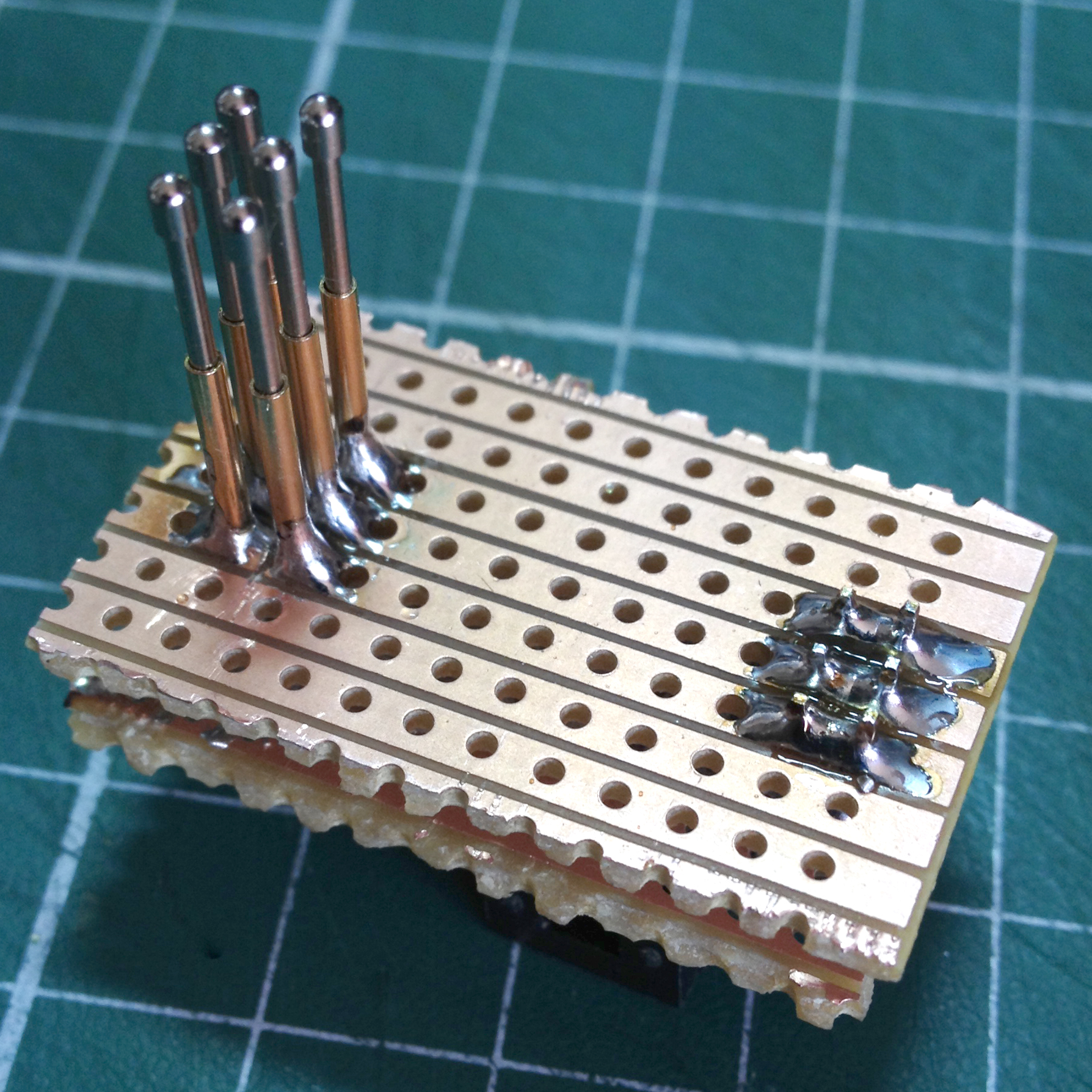
Very carefully solder the Pogo Pins taking care not to bridge across either your cuts or between the tracks (I managed to do both!). It’s worth mentioning I used the thinnest soldering iron bit I could whilst doing this.
Preparing to solder the Pogo Pins
Once you have successfully soldered the pins, you need to solder three small hook-up wires between the shrouded header connections and the far end Pogo Pins. The first diagram indicates this. By the way, can you spot the obvious mistake in the above image? Answer later on…
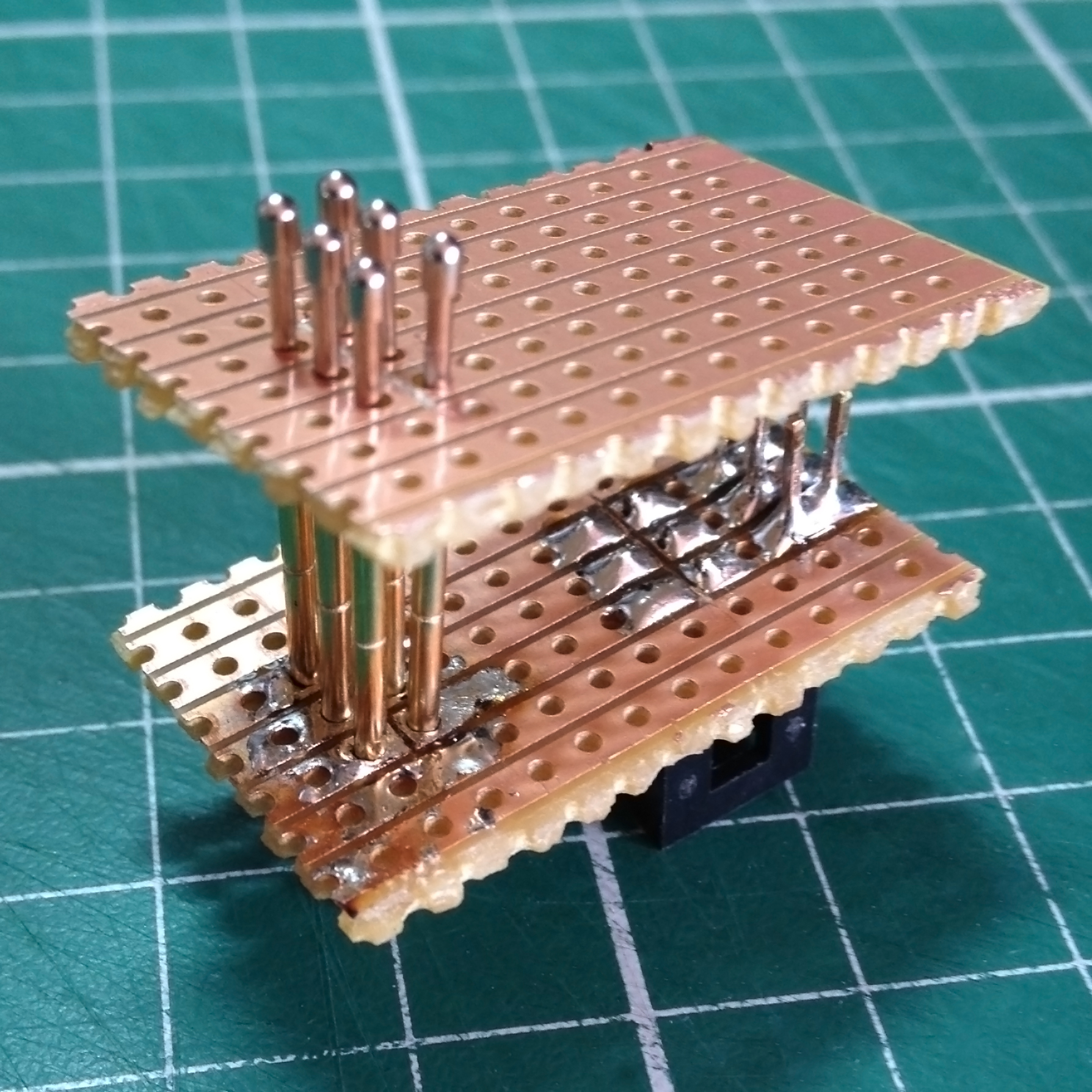
Once you have got this far, you can feed the board down the Pogo Pins and align it with the back pins on the header. This header helps to align the two pieces of stripboard correctly. Be careful not to stress the Pogo Pins at this stage. Again, take your time. Once you have fed the board down, you can solder both the header pins and the Pogo Pins.
Pogo Pins and Back Header Soldered
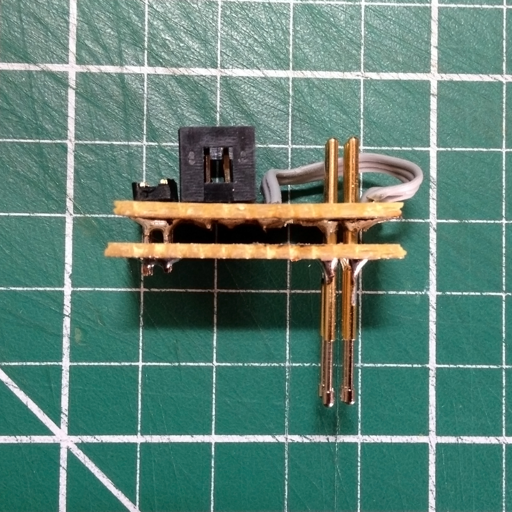
ICSP Pogo Pin Programming Adaptor – Side View
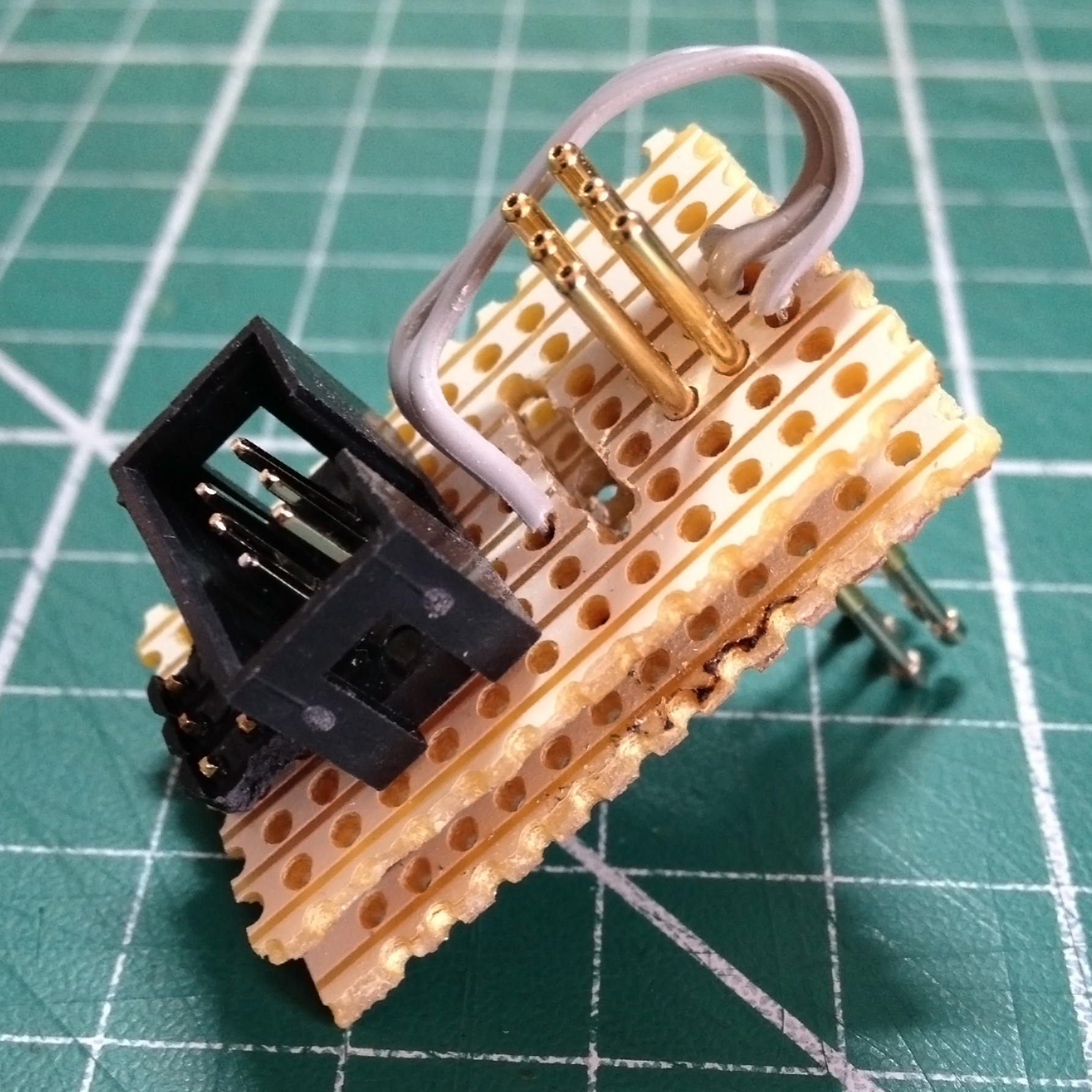
Completed ICSP Pogo Pin Programming Adaptor
Hopefully your adaptor will now look like this without the rather obvious drilling between the hook up wires and the Pogo Pins. This was the mistake I alluded to earlier. I’d forgotten one of the cuts. After assembly, the only way I could break the connections was to drill them out. A lesson learned!
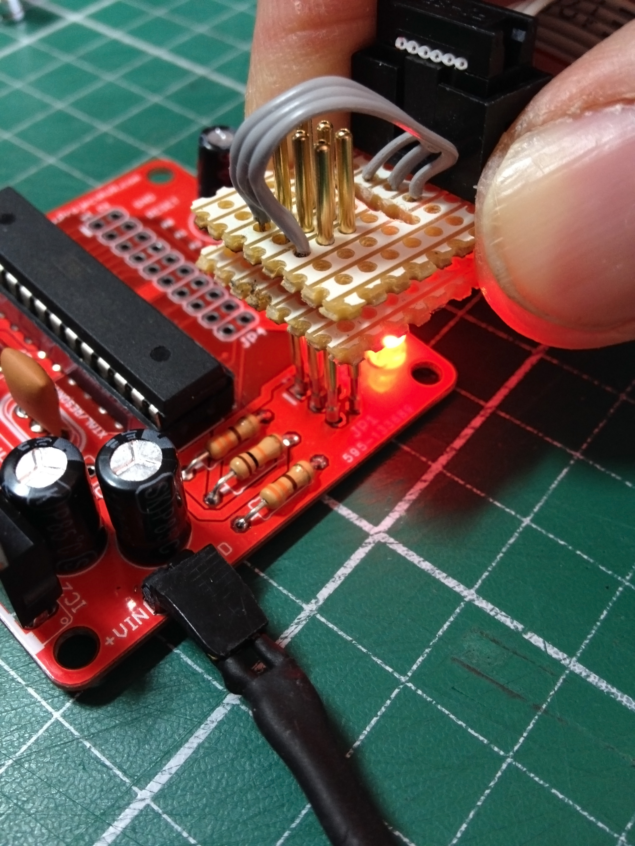
ICSP Pogo Pin Programming Adaptor in Action
Still, after all the trials of making it, the adaptor does work and it will save me a bundle in 6-pin shrouded header sockets. I just don’t want to have to build another!