Creating a PCB

To create a PCB (Printed Circuit Board), I was going to use pre-sensitized material. That is to say that the PCB has a layer of UV sensitive material applied on to of the copper layer. To create a circuit, a transparency of the layout is temporarily fixed on to the board and it is then exposed to Ultra Violet light. Any parts of the board that are exposed become soluble in diluted Sodium Hydroxide* (Caustic Soda) and parts that are covered are less so. The effect is that once the board has been exposed, you can ‘develop’ it. Any of the pattern that is left acts as a resist for the next stage which is etching.

UV Exposed PCB

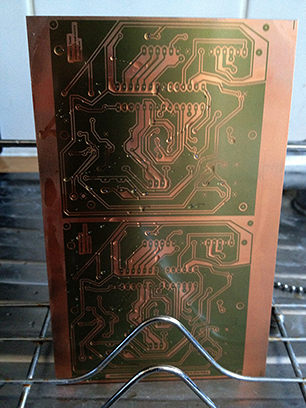
A PCB that has been exposed to UV light through a layout transparency.

This image is of the first version of the Component/Transistor tester, drying off after having been ‘developed’ in dilute Sodium Hydroxide.

Before I could perform this step, I needed to be able to make an exposure in a safe way. UV Light in concentration can be dangerous so I took that into account. I scouted the internet again and was interested to see several designs that used UV LEDs instead of glass tube bulbs. I found a batch of 100 UV LEDs on eBay and ordered two packs. I then found a likely box and thought about how to create a safe UV Exposure box.

*PLEASE NOTE: Sodium Hydroxide and Ferric Chloride are very dangerous materials and should only be handled by adults and with appropriate safety precautions. Always wear protective gloves and glasses.

Posted in Uncategorized | Leave a comment

Starting Out

I’m not sure what others would say but sometimes, I just get the urge to make something. I’ve been interested in Electronics since I was a young boy. My father taught me to solder at the age of seven (with a gas hob heated soldering iron!). So, I’m no stranger to components and building electronic projects. I’m also a radio ‘ham’ callsign G0TDJ.

Last year (2012) I became aware of AVR devices, specifically on the Arduino platform. These are amazing devices which you can turn to many tasks. Unlike the 8-bit microcomputers that I learned to program in the 80s, these devices are computers on a chip. They are termed Micro-controllers.  There are many types but all have flash rom and static ram space. Since this is all included in one chip, amongst other things like I/O (Input/Output) ports, they are pretty simple to build a circuit around and run. Programming is carried out with a few pins on the chip and is made even easier with the free Arduino IDE (Integrated Development Environment) software. Just a mouse click compiles your program and uploads it to the AVR device on your Arduino board.

I experimented with a couple of Arduino boards, namely the Uno and Mega types, just simple stuff like getting LEDs (Light Emitting Diodes) to flash on and off. I built a few things I found on the internet. There are many many designs online! This gave me a familiarity with the hardware and software. But, like so many things I’d learned before, I needed something to work towards. A goal. A project which would lead to something tangible rather than just a casual familiarity.

I begun to look for a project to satisfy my ‘itch’. I started to notice a certain project turn up again and again, built by many people in lots of variations. It was Markus Frejek’s Transistor Tester. Now, that page is in Markus’ native German but you can get Google to translate it. It works reasonably well in English. I can’t comment on other languages because I don’t speak any, mores the pity!

I was inspired by this project. It isn’t too complecated and utilized an AVR just like the Arduinos. It had been a long time since I had made a circuit, especially from the ground up so I resolved to do this. I vaguely remember making a PCB (Printed Circuit Board) with some Press-and-Peel transfer material but I was never satisfied with the results. I wanted to produce something professional looking. I resolved to use photo-sensitive PCB with UV (Ultra Violet) light. This would give the best results.

At this time, I had no UV Exposure box, no idea how to develop the PCBs (I had etched them before so I assumed Ferric Chloride was used in this case also) and no way of programming the AVRs outside of the Arduino platform which I thought would be needed. All this required careful consideration.

Posted in Introduction | Tagged , , , , , , , , , | Leave a comment

First Post – Hi

This is my attempt to document the learning process and construction of a Transistor Tester based on an Atmel AVR chip and designed by Markus Frejek. There are many variations of this project online but I wanted to show how I had to overcome several issues, one being my lack of any way to make a PCB (Printed Circuit Board), and come up with a final working result.

I will try and keep each blog post about one or a part of one component in the development. These include:

  • An LED UV (Ultra-Violet) Exposure Box
  • Exposure Timer
  • An AVR Programmer
  • Working with Eagle CAD PCB

Development continues and at the moment, I’m trying to develop an SMD (Surface Mount Device) version of the PCB.


Posted in Status | Tagged , , , , | Leave a comment