By way of a break from the Timed Camera Cable Release, I chose to develop the Electronic Film Clapper further and learned a lot in the process. I had the first iteration of the boards fabricated by Hackvana as usual and they arrived in good time.
On the board, I included several options to tailor the design to the builders taste. Provision for both a digispark board or bare ATTiny85 chip, small or large tact switches and a jumper to defeat the LEDs supply resistor for extra brightness.
I chose to build the Digispark version first. It went together easily (bar a hole size issue, more of that later) and I programmed the digispark via it’s own USB socket. And… the board completely failed to start up. It took me some time to realise that I’d got the USB power connections inverted! Lucky I’d added a reverse polarity diode! I de-soldered the USB ‘A’ type plug and re-soldered it on the back side of the board flipping the connections. I don’t have the correct type of USB plugs anyway, so it’s a bit of a kludge at the moment. However, once this was done, the board sprung to life. When powered up, the Digispark’s micronucleus bootloader kicks in for a few seconds and then the Clapper code starts.
The hole size issue was due to my custom tact switch footprint in KiCad being wrong. Although I managed to transfer the dimensions across from the datasheet successfully, I’d used the wrong size drills for the through plated holes and hence, the larger Omron type tact switch will not fit. I have amended the footprint now. At the moment, the switch on the prototype board sits slightly high on the surface.
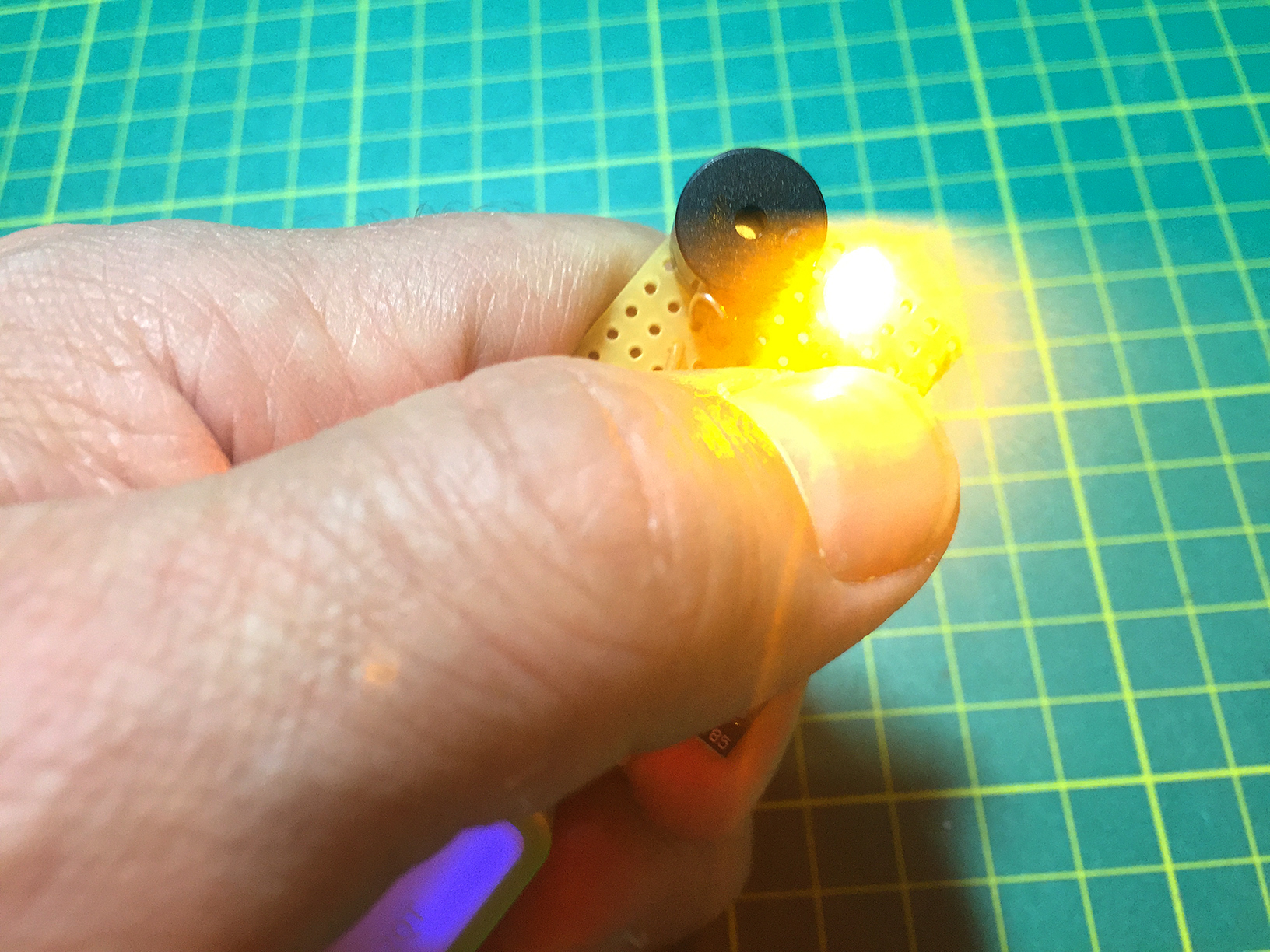
There was another issue to be resolved; although the board started up fine, the ‘pip’ seemed to be incomplete. It was obvious from the symptoms that there wasn’t enough power to flash the LED and sound the pip at the same time. To sort this problem out, I bridged across the 78L05 part of the circuit. Once I had done this, the board worked perfectly.
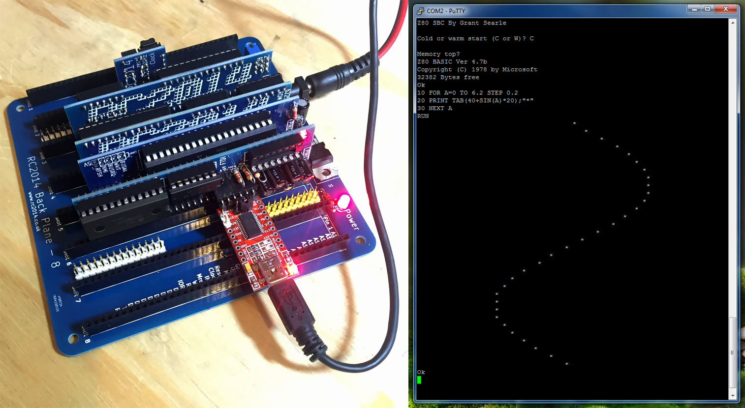
So, on to the bare chip version. Having learned of the tact switch problem on the first build, I elected to use the smaller tact switch on this board. It fit perfectly. I had it complete in short order. I programmed the ATTiny85 chip via a technique called ArduinoISP where an Arduino UNO becomes a programmer. Upon powering the board up… Flash but no pip. This frustrated me for several days. I tried many fixes including changing the ATTiny’s fuses, but finally discovered that the bare ATTiny85 doesn’t directly support the Tone() function which is what I used in the code for the pip sound. I can only assume that the Digispark has custom code to account for this.
After a lot of research, I discovered an article on Technoblogy detailing this issue and a pointer to a library that adds the functionality. Once I re-programmed the ATTiny85 all was well!
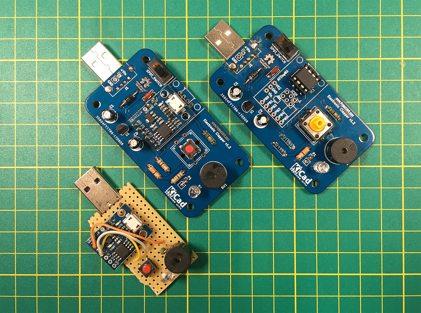
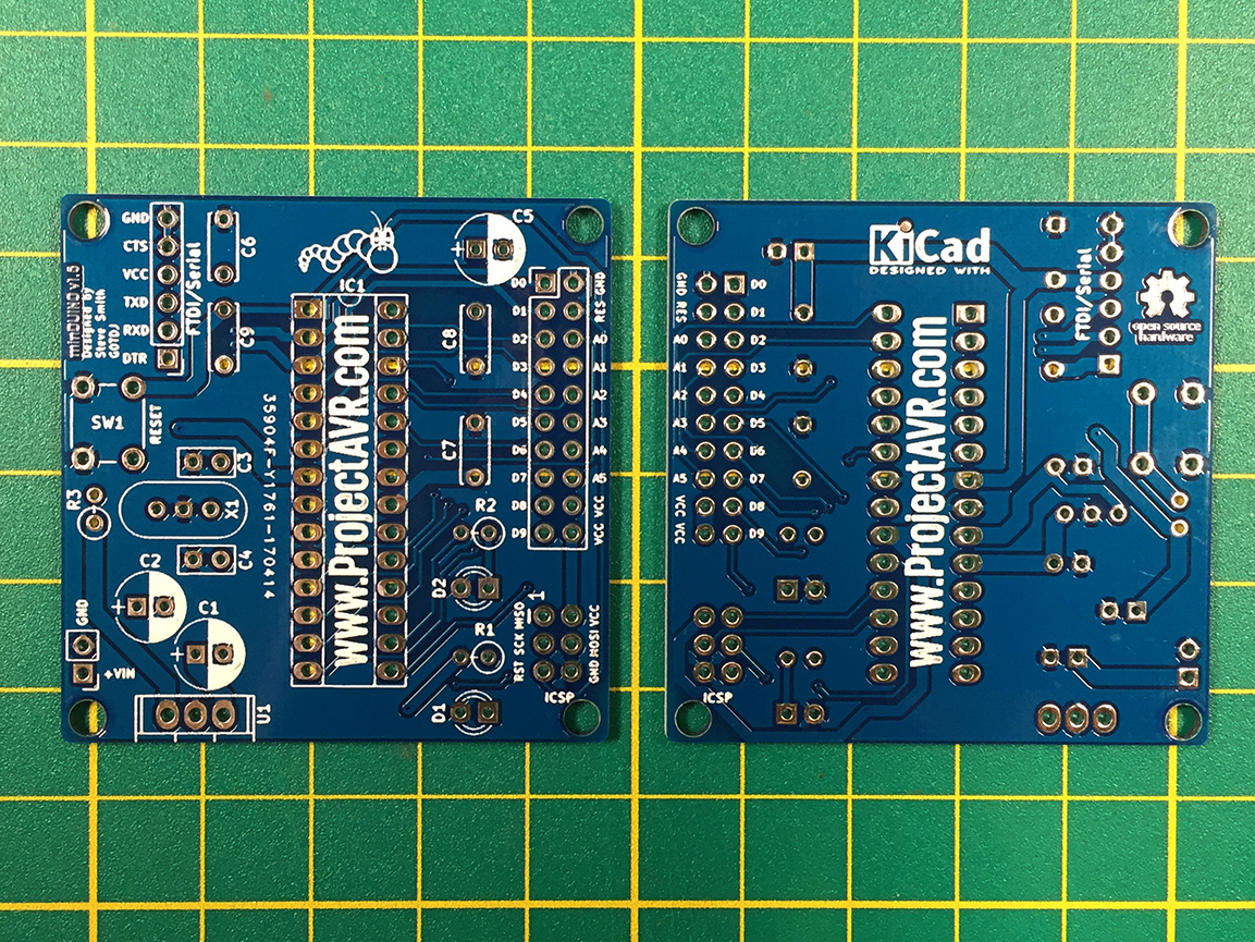
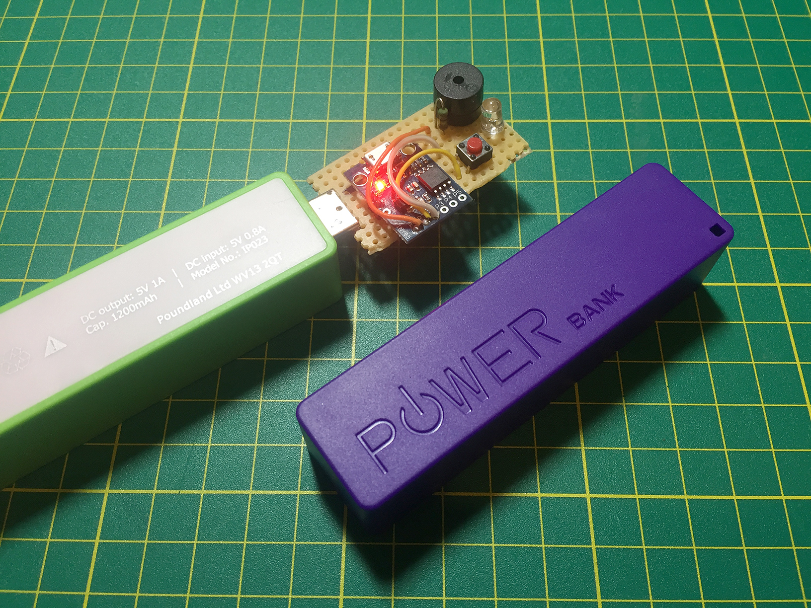
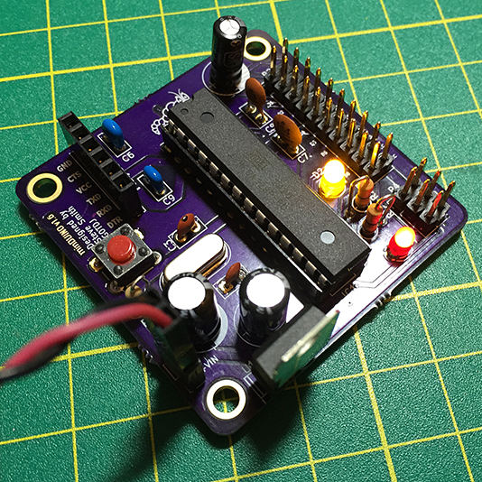
Film Clapper prototype and v1.2 boards
To finalise the design, I’ll be inverting the USB Type ‘A’ plug, removing the regulator circuit and making provision for a link across the buzzer resistor. I have found that driving both the buzzer and LEDs directly from the ATTiny’s GPIO lines gives a much brighter LED and louder ‘pip’. I would imagine that this stresses the ATTiny slightly but since it’s a brief pulse, and provided it’s not done repeatedly, I believe it will be OK.
Design files are available on the AVR Projects page.