Distributed Computing

Now for something slightly different. In attempt to support this site and a few others that I have online, I’ve looked into ways of earning a few pennies. You may have noticed the (hopefully) few Google ads on the pages. I have discovered another money making technique in the shape of distributed computing. I have long known about this since I ran the SETI@Home software for ages (searching for intelligent life via the Aricebo Radio Telescope). This is slightly different in that the data that each workstation processes does so to test websites and pays the user for doing so. In their own words:

“Gomez PEER is a secure java application that runs in the background of your PC and leverages your system’s idle resources (such as unused processing power, RAM, and bandwidth) to test the performance of many of the world’s most popular websites.”

As the text says, you run a small Java app on your desktop and it uses spare processor cycles. There is a probation period whilst the software works out if your workstation will be useful after which it makes the Java app active. I have been running it for a few days and have potentially made the hansom sum of $0.15! I expect this will grow once the app has been running for a while and goes into it’s active state. The thing to do is to leave it running all the time whether you are using your workstation or not. Since mine runs 24/7, that won’t be an issue for me. It’s not exactly going to make me rich anytime soon but with a few referrals,  it may help with the hosting fees.

If you’d like to give it a try, please click on the banner below which will automatically add me as a referrer. If this doesn’t work, please indicate ‘destinysagent’ without the quotes as your referrer when you go through the sign-up process.


Any help given is very much appreciated and helps with hosting a variety of websites including this one.

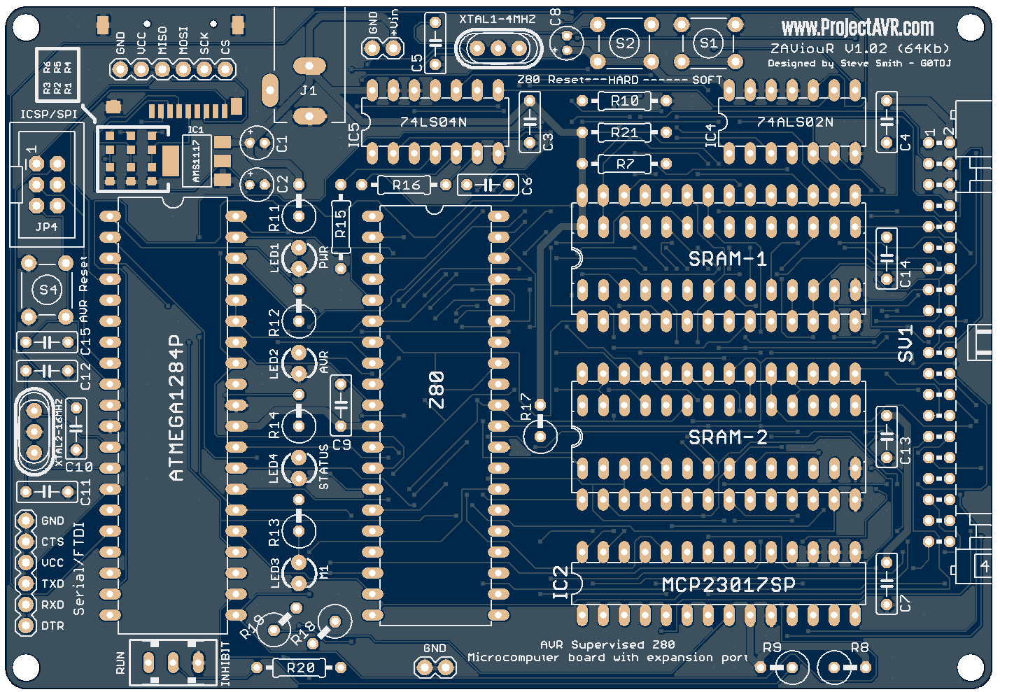
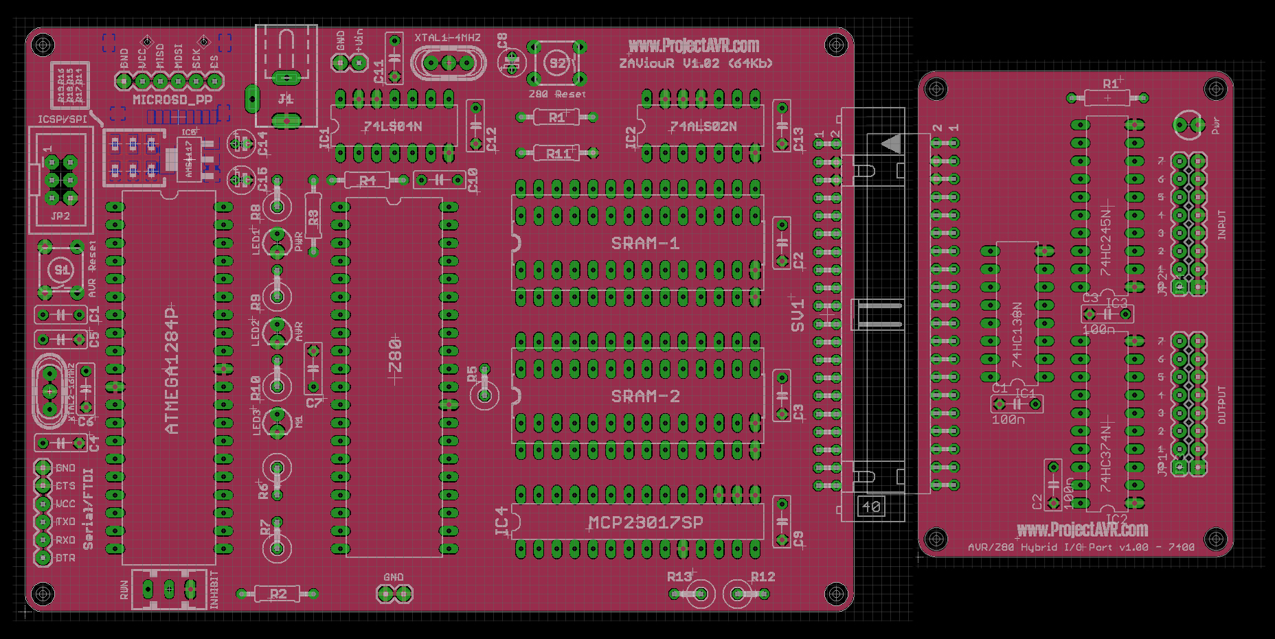
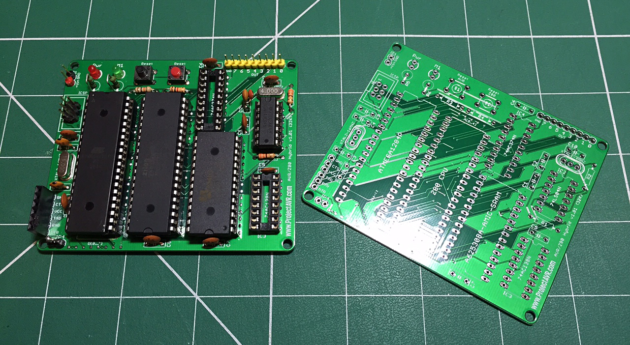
In other news, I have given the ZAViouR Board a little break, having run up against a few software problems. I aim to be back with it once I complete a few other projects I’m currently working on.

Posted in Coding | Comments Off on Distributed Computing

New Boards On The Way

Finally, after being involved in non-electronic projects for a while, I’ve been able to finalise the new ZAViouR board v1.02 and the 7400 based I/O expansion board v1.00. Both have been sent to my favourite fabrication house, Hackvana and I await the acceptance e-mail.

ZAViouR v1.02 Gerblook.org Preview

ZAViouR v1.02 Gerblook.org Preview

Meanwhile, I’ve also started on an 8255 based I/O board, a Zilog Z80 PIO based I/O board and of course, the Backplane board. After the ZAViouR and 7400 I/O boards have been tested, I’ll get the backplane fabricated.


I’ve arranged the expansion connectors so that the backplane will replace the I/O board and the I/O board and up to three others may be plugged into the backplane. The backplane has now an optional daisy-chain connector so that more than one can be connected.

ZAViouR Backplane v1.00 Eagle Preview

ZAViouR Backplane v1.00 Eagle Preview

The I/O board and Backplane required a specially mirrored 40-pin IDC connector which I created as a custom component in Eagle. There is no difference in the physical connector, just how the connections are utilised on the PCBs.

Once tested, all the design files will be available on their own page which I will add to the site.


Posted in Construction, Design, ZAViouR | Tagged , , , , , | Comments Off on New Boards On The Way

ZAViouR Demo and plans

Development continues on ZAViouR Boards v1.01 and v1.02. With a simple bit of Arduino code, you can insert Z80 Hex coded machine code into the ‘Sketch’ via bin2h.exe then compile and run it. Demonstrated here with a simple routine to flash LEDs on the output port:

I recorded the clip on my iPhone which misses LEDs due to it’s frame rate. In reality, all the LEDs flash in turn before repeating.

Meanwhile, I’ve also been developing ideas for the next iteration of ZAViouR adding the following features:

  • A 40-pin expansion port.
  • SRAM size Option. Extra traces for Cypress CY7C199CN 32K SRAMs.
  • A ‘proper’ power socket.
  • A second indicator LED for AVR status.
  • A Run/Inhibit switch to tell the AVR to run or stay ‘Hands Off’ at start up.
  • A Micro-SD Card socket and header to provide storage via the AVR.

I have produced a quick mock-up of the new board along with the I/O board I’ve designed to go with it based on a single port of Grant Searle’s excellent design.

ZAViouR with I/O Expansion

ZAViouR with I/O Expansion

My intention is to get the I/O Board fitted and proved before designing a backplane board that will go between them and add three more ports.


Posted in Building, Construction, Design, ZAViouR | Tagged , , , , , , , , , | Comments Off on ZAViouR Demo and plans

ZAViouR Lives!

After a painful few days programming, trying to identify why I couldn’t do a simple thing like load SRAM with data, I found that I’d mis-typed one of the port names in the init routine. After editing the single character that was incorrect, it sprang into action!

I quickly modified the program to load a ‘proper’ Z80 routine and tried it out. It was a simple program, loading 50 bytes of RAM positioned just about the main code with a value. I first ran the AVR code to load the Z80, then manually switched off the /BUSRQ line (a modification I had to hardwire to the board) and reset the Z80. I then ran a read program on the AVR and the value I’d chosen was there in the SRAM! I changed the value a couple of times and re-ran the test to verify it was working.

;Z80 Test Program

DESTINATION_SIZE equ 50
.org 0000h
start:
LD HL, Storea                                    ; point to the source
LD DE, Storea + 1                              ; point to the destination
LD BC, DESTINATION_SIZE – 1      ; copying this many bytes
LD (HL), 170                                      ; put a value in the 1st pos
LDIR                                                  ; move 1 to 2, 2 to 3…
Finish:
NOP
NOP
NOP
NOP
JP Finish                                              ;Infinite Loop
Storea:
DEFS 50

end

The next step is to re-write the loading program entirely, in a more tidy manner, and test the Z80 properly when the two missing chips for the output port are delivered.

I’d like to say a big thank you to Bill Rowe who gave me some great advice and suggested ideas as I went along. I’m sure I will find his help invaluable in the future as I develop the ZAViouR Board.

For those who would like to follow the progress as it happens, I have a Hackaday.io page devoted to the project. You can find it at: Hacakday.io

 Here’s a quick video of me resetting the board twice. You can see the /M1 light flicker (once I get my hand out of the way!) and then go off and on as the Z80 resets.

In the video you can also see the hard-wired /BUSRQ switch which will be re-routed to the AVR in the next version of the board. The next version of the board will have improvements based on experiences with the current version. It will have 64Kb of SRAM and the address lines will be driven from the AVR via a port expander. This will free up plenty of AVR GPIOs for other tasks.


Posted in Uncategorized | Comments Off on ZAViouR Lives!

AVR/Z80 Hybrid

The AVR/Z80 Hybrid boards arrived yesterday. Excellent service as always from Hackvana, my preferred fabricator. I set about constructing the first board. I’ve not included the output port on the first one since I haven’t got the two relevant 74′ chips in stock but they are on order and not necessary for initial testing.

AVR-Z80 Hybrid v1.01 Assembled and Bare

AVR-Z80 Hybrid v1.01 Assembled and Bare

It went together pretty easily. I soldered the chip sockets first, then the capacitors and then followed with the rest of the components. The Z80 is an original Zilog chip, one of a few I own. Before inserting the AVR, Z80 & AMIC SRAM, I tested the 7404 oscillator and all was well. I then plugged in the AVR and tested it by loading the standard ‘Blink’ program via ICSP, OK so far. I added the Z80, still OK and then the SRAM – Ooops! Dead short (indicated by my PSU going into Constant Current). After a quizzical few moments I realised I had plugged it in backwards! Doh! Luckily, I have a number of this chip if this one has failed but I reversed it and all is well.

I have started writing some test code which I will publish when complete and working. At the moment, the code is getting the AVR ports set up for sending data over to the SRAM. I’m currently working out the best way to convert a Hex or Bin file into something that the Arduino IDE will accept as data in preparation for sending byte by byte over to the SRAM.


Posted in Construction, Programming | Tagged , , , , , , , , , , | Comments Off on AVR/Z80 Hybrid

Universal Regulator Board

I have just published my design for a Universal Regulator Board in the Non-AVR Projects section. The idea behind it was that I was using much the same power supply for the majority of my projects, a 7805 and associated components. I thought it would be a good idea to design a PCB that could be configured to accommodate any of the 78XX devices and also the 78(X)XX devices (i.e. 78L05).

Universal Regulator Board v1.0 Gerblook Front

Universal Regulator Board v1.0 Gerblook.org Front

It features a polarity protection diode on the input, an optional power LED fed from the output and a snap-off heatsink support. Having built and tested one I found the snap-off to be a little stronger than I had imagined! However, it’s still functional.

I have already begun designing a new version with capability for more regulation devices. This will be released once fabricated by my favorite PCB fabrication house, www.hackvana.com, and tested but to whet your appetite:

Universal Regulator Board v1.1 Eagle Preview

Universal Regulator Board v1.1 Eagle Preview

This new version will be configurable for 78(X)XX, LM1117T and LM317 Variable Voltage regulators.

Another up and coming project is an AVR/Z80 Hybrid board. I’ve been a fan of the original Z80 microprocessor since the 80s when I used to program/hack and generally muck around with Sinclair Spectrums. For a goodly while now, I’ve had an itch to do some Z80 machine code programming just like in ‘The Old Days’ so I designed a board that accommodates a Z80 with 32Kb of SRAM, supervised by an Atmega1284.

Z80-Arduino Hybrid v1.01 Gerblook.org Front

Z80-Arduino Hybrid v1.01 Gerblook.org Front

The board includes a power light, an M1 indicator to show the Z80 running, reset switches for both the AVR and Z80 and an 8-bit output port for testing. This is very much a prototype and won’t be published on this site, however, if it proves to be successful, I have plans to double the SRAM and give the board a ‘proper’ expansion port. That design, if successful, will be published along with some sort of basic I/O expansion.

Initially, the AVR will have Z80 binary hard-coded into it so that when the board starts up, the AVR will suspend the Z80 with it’s /WAIT line, load the SRAM with the binary, assert the Z80’s /RESET line, drop the /WAIT and then drop the /RESET releasing the Z80 to run through the code in the SRAM. That’s the plan anyway.

Stay tuned…


Posted in Building, Construction, Design | Tagged , , , , , , , | Comments Off on Universal Regulator Board

ESP’ecially good!

The ESP8266 ESP-01/03 Flash/Proto v1.4 boards arrived today. I set about building one up to test it and it all checks out.

ESP-01-03 Flash-Prototype Board v1.4

ESP-01-03 Flash-Prototype Board v1.4

I used my usual SMD soldering technique of placing blobs of solder paste on each of the connections with a pointed tool and using an SMD rework station to melt the solder.

SMD Soldering by hand

SMD Soldering by hand

It’s not pretty but the PCB is readily cleaned with Acetone after all soldering is done (Read safety guidelines before using Acetone). My SMD soldering process is more fully explained in my earlier post: SMD Soldering Technique on my other website www.ProjectHAB.co.uk

The ESP8266 Flash/Proto boards were fabricated by the excellent Hackvana to their usual standard. Even the smallest silkscreen text is readable, even if I do need a magnifying glass to read it!

Having now tested the first board, I’m have published the design files on their own page: ESP8266 ESP-01/03 Flash Prototyping Board


Posted in Building, Construction, ESP8266 | Tagged , , , , , , | Comments Off on ESP’ecially good!

ESP8266 ESP01/03 Flash-Prototype Board

The ESP01/03 Flash-Prototype Boards arrived from the fabricator. Good quality boards in a reasonable time. Although not Hackvana (Sorry Mitch, I’ll be back for the next batch!).

ESP-01-03 Flash-Prototype Board v1.3

ESP-01-03 Flash-Prototype Board v1.3

Here you see two of the boards, one populated with an ESP-01 module, the other with an ESP-03 SMD module. Both work well but I have since found out that the ESP-03 module requires GPIO15 to be to be LOW during normal running or programing. Also, GPIO2 needs to be taken HIGH along with GPIO0 being taken LOW for programming. Hence the flying leads on the ESP-03 illustrated.

I am in the process of updating the board design to accommodate these changes and I’ve also taken the decision to make it fully SMD. This will make the board more compact and easier to use for IoT applications.

ESP-01-03 Flash-Prototype Board v1.4 SMD Gerblook

ESP-01-03 Flash-Prototype Board v1.4 SMD Gerblook


Posted in Design, ESP8266 | Tagged , , , , , , | Comments Off on ESP8266 ESP01/03 Flash-Prototype Board

Distractions (ESP8266 Flash Board)

Lately, I’ve been distracted from general AVR stuff by the now ubiquitous ESP8266. I purchased a few ESP-01 boards and an ESP-03 board a while before moving location and I’ve just got around to learning a little about them.

The first thing I did was rig up a small strip board PCB to aid in the programming. At first, I was powering the ESP module from the USB to Serial adaptor but I found that it wasn’t man enough. I modified the board to accept external power from my bench PSU and disconnected the +3.3V line from the adaptor.

ESP-01 Prototype Programming Rig

ESP-01 Prototype Programming Rig

This was just intended as a quick solution until I designed a proper PCB. Meanwhile, I discovered that you can use the Arduino IDE to program the ESP modules. I’m very familiar with the Arduino IDE so I installed the files required after downloading the latest Arduino software.

Having gotten interested in the ESP modules, I did some searching and one of the websites I came across was www.openhomeautomation.net Here was documented a way of logging Temperature and Humidity from a DHT11 unit connected directly to the ESP-01 module. You can see a DHT11 in the previous image in the top left of the PCB. I duly followed the instructions on the Cloud Temp/Humid Logger page and lo and behold, I had Temperature and Humidity values displayed on Freeboard (May not be up to date or accurate).

Although I had made the prototype configurable for programming and reading from the DHT11, I really wanted a dedicated board I could use, and one that would allow me to utilise the ESP-03 module that has lots of GPIO pins broken out. I set to work designing a board in Eagle.

ESP8266 Flash Board v.1.3 Eagle Preview

ESP8266 Flash Board v.1.3 Eagle Preview

This is the result. A general purpose board able to accommodate either the ESP-01 or ESP-03 modules. The power source is selectable from either the USB to Serial input header or a Micro USB connector/standard 0.1 pitch header. In the latter case, the voltage is regulated to 3.3V by the LM1117T device. The board also features a 3.3V zener diode on the RX pin of the modules to prevent over voltages over serial, a reset switch, power indicator LED and GPIO header.

Once the boards have arrived from the fabricator and I have checked them over, the design files will be available on a dedicated page licenced under Creative Commons Attribution – Share Alike v4.0 for anyone to use as they see fit.


Posted in Uncategorized | Comments Off on Distractions (ESP8266 Flash Board)

New minDUINO Variant.

Way back last year, before all the hassle that moving location entails, I started to design a minDUINO variant to work with the UKHASNet mesh network. Finally, having gotten settled down, to a degree, in my new location on the south coast of England, I have been able to continue.

I have designated the new board as minDUINO v1.6b. The major difference to the previous boards is that it runs on 3.3v rather than 5.0v. It utilises an LM-1117T regulator. Apart from that, it’s pretty much the same as versions 1.5, 1.6 & 1.7 apart from the additional resistor network, an ESP8266 WiFi module and an RFM69HW module for radio duties.

MinDuino v1.6b UKHASNet Node

MinDuino v1.6b UKHASNet Node

The RFM69HW is integrated on to the main board and the ESP8266 plugs into the header at the top of the board next to it’s associated component C10. Being based on the minDUINO, it retains all the programming and GPIO headers. I have added a header to access the RFM69HW’s GPIO ports as well. JP9 gives access to monitor the supply voltage pre regulator by connecting Vin to ADC0 on the ‘328 micro-controller and JP5 connects an optional indicator LED to D10 which the previous versions were hard-wired for. On the latest iteration of the board (not shown), there are also two through-hole test points to monitor the regulated voltage.

I have found it useful in the past to let a design sit for a while so that my brain can view it afresh and spot any glaring mistakes. My intention is to do so before having some PCBs fabricated by Hackvana. Eventually, the design will be published on the main minDUINO page under the Creative Commons Attribution Share Alike licence v4.0 for anyone to utilise as they see fit.


Posted in Uncategorized | Comments Off on New minDUINO Variant.