In my last post, I described the steps I took to prepare for refurbishing a 48K Rubber Keyed Sinclair Spectrum. I am now going to describe how I replaced all the electrolytic capacitors, or Re-Capped the board.
Firstly, I extracted the board from the case by removing the five screws on the undereside of the case. I then carefully flipped the entire case over and carefully removed the top. I did this slowly in order to safely unplug the membrane ribbons. If you open the case to enthusiastically, you can damage the membrane ribbons which will probably result in a replacement being needed. I gently disconnected the ribbons from the board and put the top of the case aside, ribbons upwards. It was then a simple case of removing the single silver screw near the center of the board to lift the board clear of the lower half of the case.
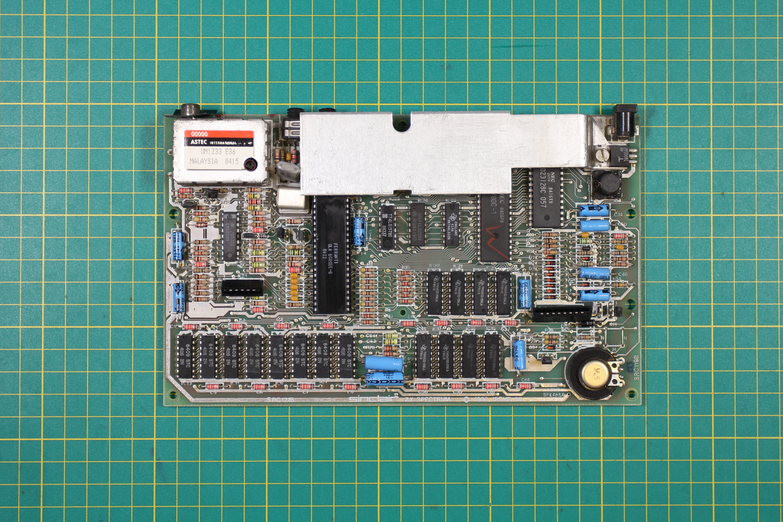
Bare Sinclar Spectrum 48K Board
The kit of capacitors that comes from Retroleum is very comprehensive. There is at least one capacitor for every one in several models of 48K Spectrum. I have re-capped several boards with the same kit and there’s always spares (into my stock they go!).
My technique for replacing the capacitors is to use a hand de-solder pump and to work methodically across the board, doing one capacitor at a time. This gives you time to check and double check which way around the components fit and to make sure you get the correct value from the capacitor kit.
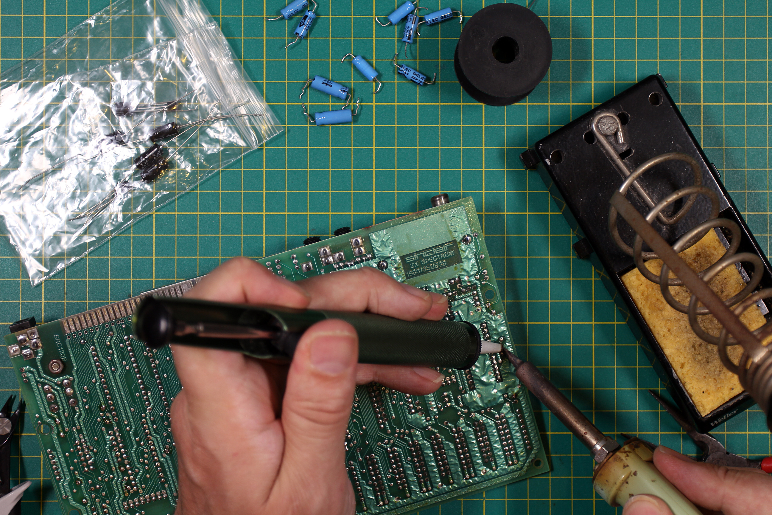
Methodical De-Soldering
Check out my ancient Weller TCP-FE soldering iron, still working fine after over 30 years of use! It’s never failed me.
I extracted each capacitor carefully, so as not to damage the traces on the board. These can be damaged easily so I only heated joints when necessary and tried to remove component leads gently. Easier said than done with stubborn leads but patience is king here. If necessary, balance the board on it’s edge, hold the component lead from the top side of the board with a pair of long nose pliers and heat the joint from below the board. Go slowly and pull gently. Only pull the component lead when the joint is adequatly heated otherwise the component will be released too fast. If your de-soldering pump is doing it’s job properly, this should seldom be required.
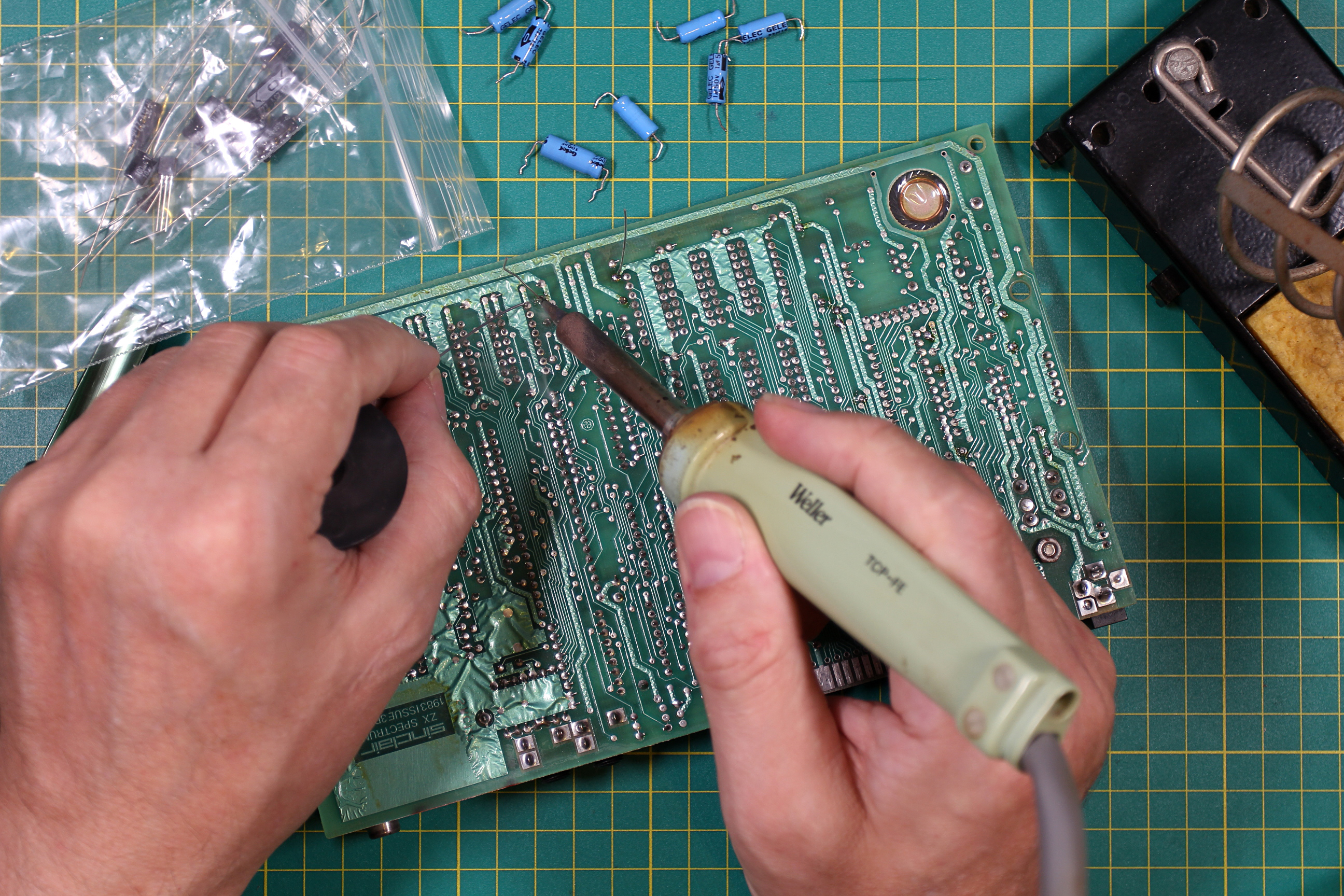
Soldering In the New Component
One thing I am a stickler for is neatness in my work. Neat work is good work and makes things easier later on. To this end I bent the components leads at right angles with the help of long nose pliers, a little distance away from the components body. I roughly measured the first couple I did to get an idea of where exactly to bend them. Bending the leads away from the components body affords some strain relief when the component expands and contracts with temperature. Another thing I make sure of is to make sure the components labels are facing upwards. This is not only neat but would help later if any required replacement. Once soldered. I clipped each lead by holding the free end and clipping close to the board. By holding the leads when you do this, it avoids them flying out of control and avoiding potential eye hazards. I have a large coffee tin where I put these off-cuts because they come in very useful for short links and other tasks.
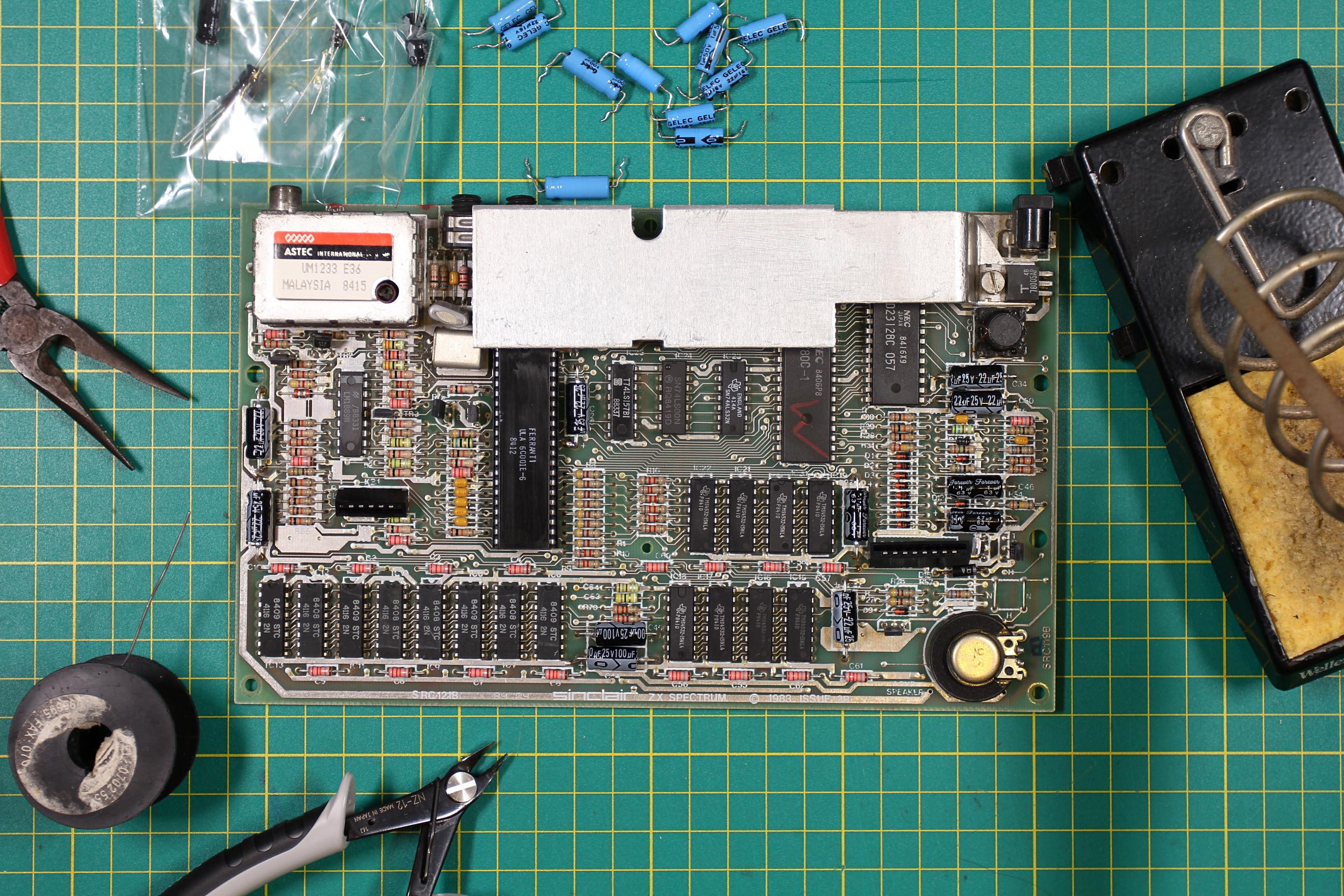
Freshly Re-Capped Spectrum
When you have completed the re-capping, examine all of the joints even if you have been checking them as you go. It is really easy to miss a’dry’ joint and is difficult to find later. If you see any joints you are not happy with, simply reflow the solder and add some fresh for a good joint.
When finished, I would usually test the board but I was confident I’d done a good job and I was going to move striaght on to replacing the power regulator next in any case. I will describe that process in the next part of this series.