As I had assertained earlier, the 48K Rubber Key Spectrum I was refurbishing required it’s Upper RAM to be repaired. Since the chips inside of the machine were old, I elected to replace them with a complete Upper RAM Module. This had the benefit of fitting IC Sockets onto the board if ever I wished to re-fit original ICs in the future.
Preparing for Upper RAM Replacement
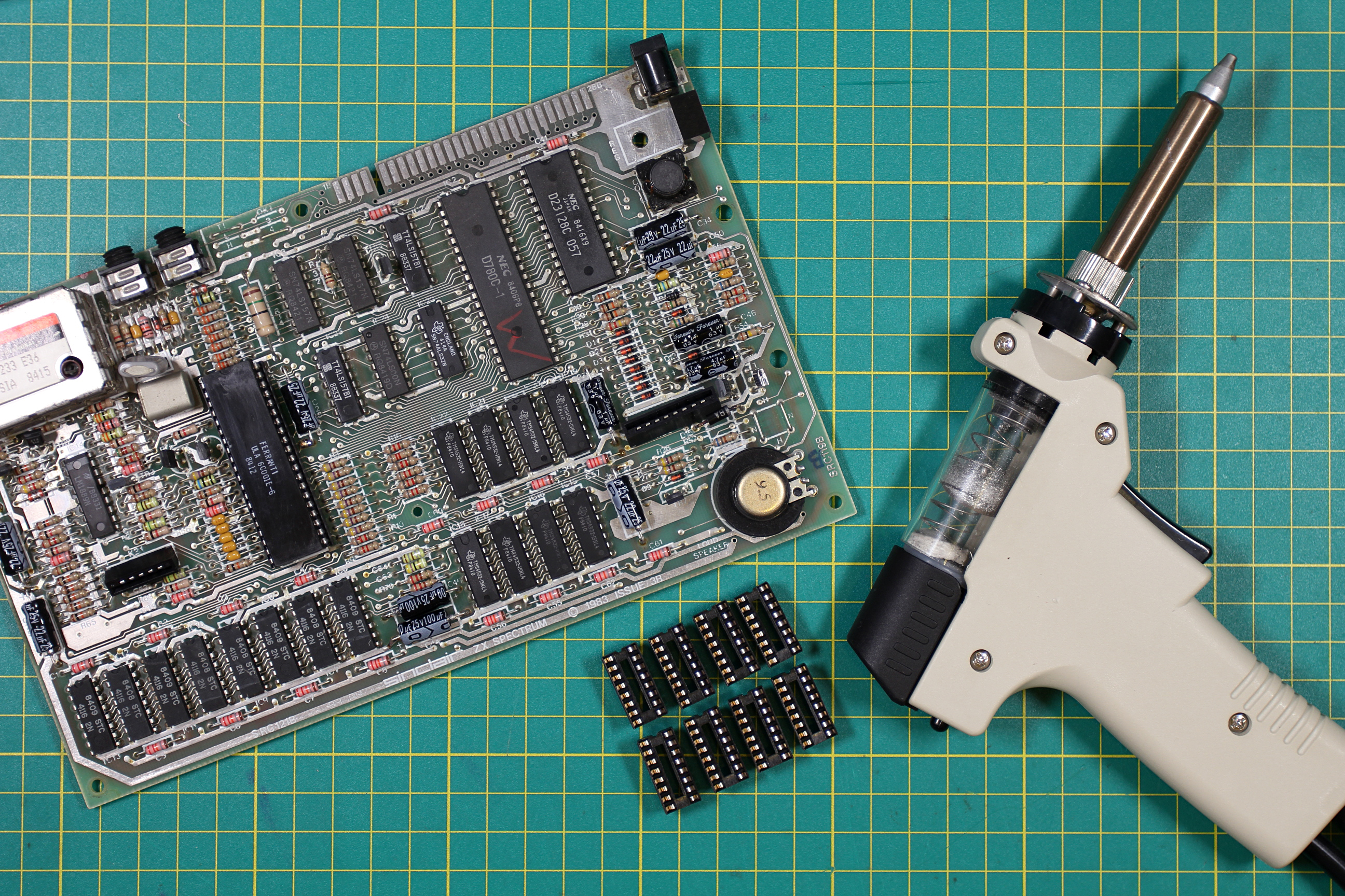
I am really lucky in that I have a ZD-915 De-Soldering Iron at my disposal. I could have used a hand de-soldering pump but the de-soldering iron makes life a lot easier. With both tools, it is essential you take your time and don’t overheat the connections. The tracks on the board are quite delicate and are prone to lifting off of the PCB (as I found in a previous replacement!).
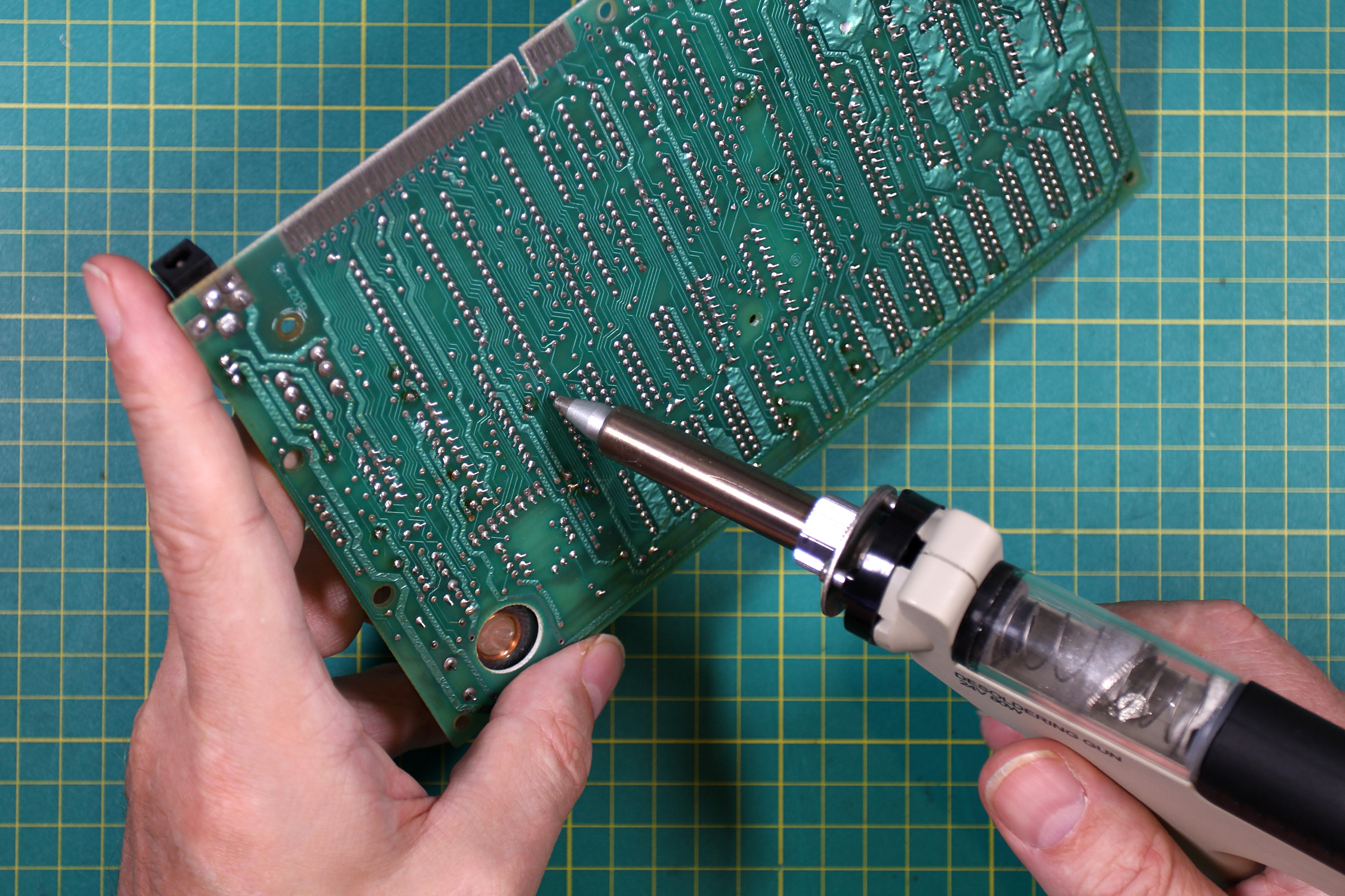
De-Soldering Iron In Action
As with a hand de-soldering pump, you need to let the solder liquify before triggering the iron’s electric pump. I found it was helpful to make small gentle orbits around the connection whilst the machine sucks away the solder. Don’t scratch the board whilst doing this, only the lightest touch is required. Some joints are really stubborn and I found it easier to leave these until the end so as not to break up the rhythm I’d developed. Once all the other connections have been dealt with, I used my normal soldering iron to add fresh solder to the stubborn joints, giving them plenty of time to heat up and flow through the plated through-holes. I then re-tried the de-soldering iron and they became free of solder without issue.
After de-soldering the connections, I found it was worth going through each of them with a normal soldering iron and pushing the pins into the center of their holes, to fully free them from the sides of the through-holes. This prevents the plating being lifted out with the ICs.
The next step was to very gently lever the ICs out from the board. I found that the ICs were still quite firmly secured and required a moderate force to free them. I did this by using a small screwdriver on the corner of the chip and levering against a part fo the PCB that didn’t have any tracks. If you feel you are putting too much pressure on the connections, you probably are! Go back and see if you can free them any better with a soldering iron in this case. When the chips began to lift, I pushed the screwdriver in further along the base of the IC, making sure not to scratch the board. When you have successfully lifted an IC, check the legs to make sure you haven’t pulled out any plating as well (You may see some solder though)
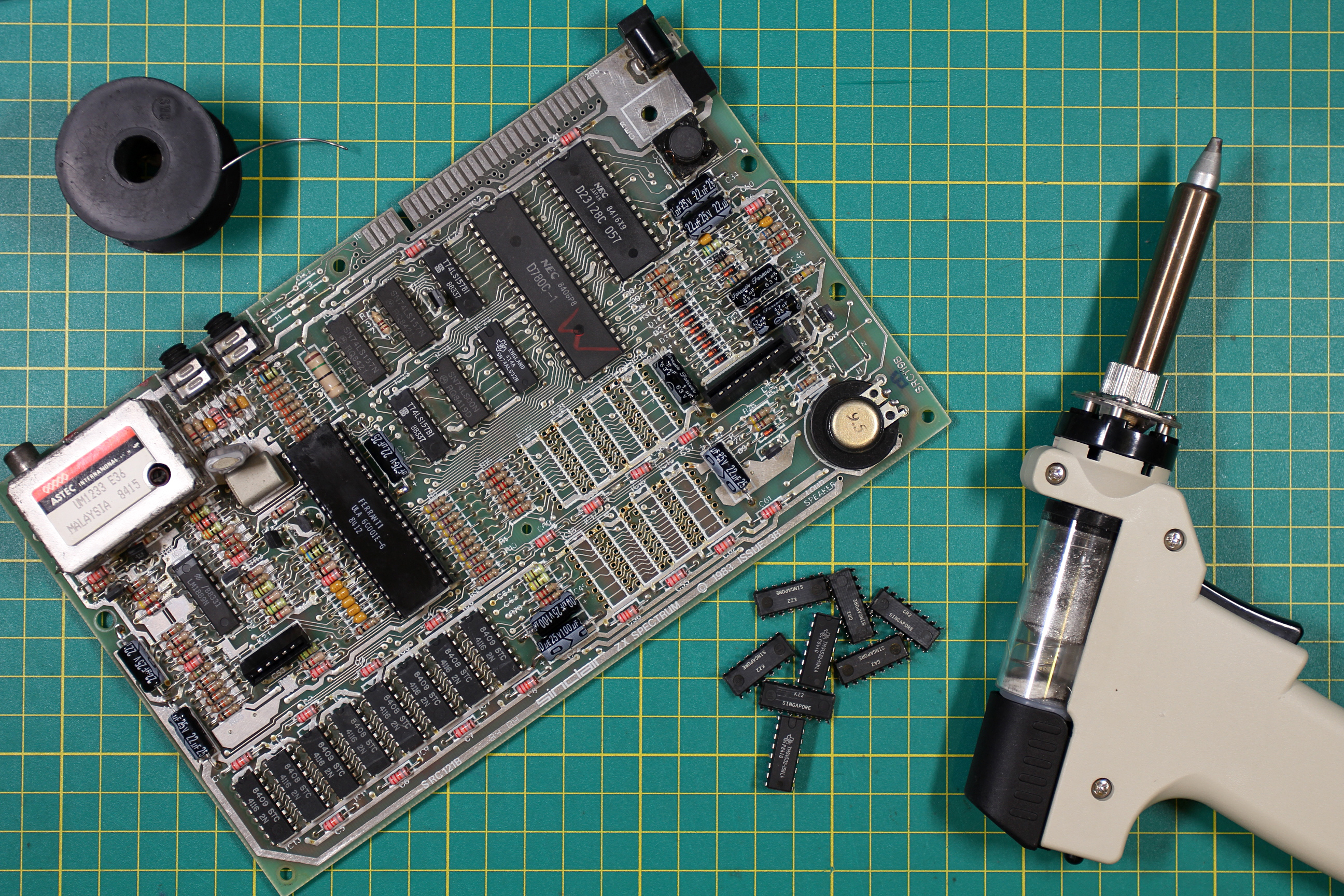
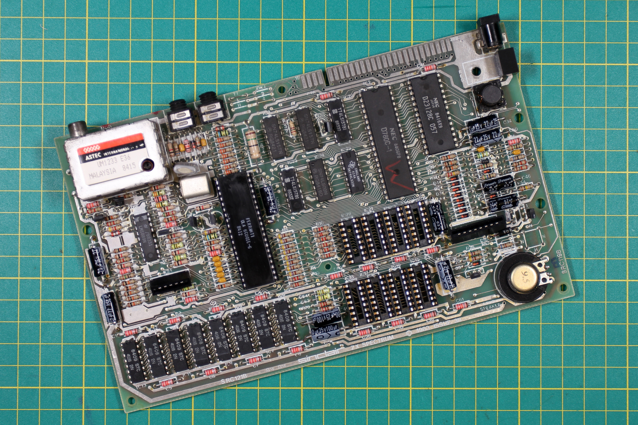
Upper RAM Chips Removed
Even though you have checked each IC’s legs for plating, double-check the board for any damage. I managed to remove all the chips on this board without causing any damage at all. Next, I found 8x 16-pin IC Sockets and soldered them in one at a time. I used our old friend, Blu-Tack to assist. My personal technique is to place the IC Socket in the board, checking I have the Pin-1 notch indicator at the correct end. Then affixing some Blu-Tack on the side to prevent it from falling out, I then solder the top left and bottom right connections. After this, the Blu-Tack can be removed and the socket checked for being flush to the PCB. If not, it is a simple case of re-heating the joint required and pushing the socket down whne the solder is molten. Once the socket is completely flush, you can solder the rest of the connections. I also tend to check the connections with a magnifier to make absolutely sure I haven’t bridged them or missed any out.
Upper RAM Sockets Soldered In
I find a slow, methodical approach to this kind of work pays dividends in less mistakes and good quality workmanship.
The final step was to fit the new Retroleum Upper RAM Module. This is simplicity itself. You just have to line up the top-left pin on the module with the top-left Pin 1 of the Upper RAM IC Sockets and give firm push down. Do this on a nice flat surface. All the instructions for this are included with the module kit.

Upper RAM Module Fitted
Now, to test the board. For this I used a Bytedelight ZX-HD interface that provides HDMI output from any Spectrum. I feed the signal into a HDMI to VGA Adaptor to use along with my Dell VGA screen.
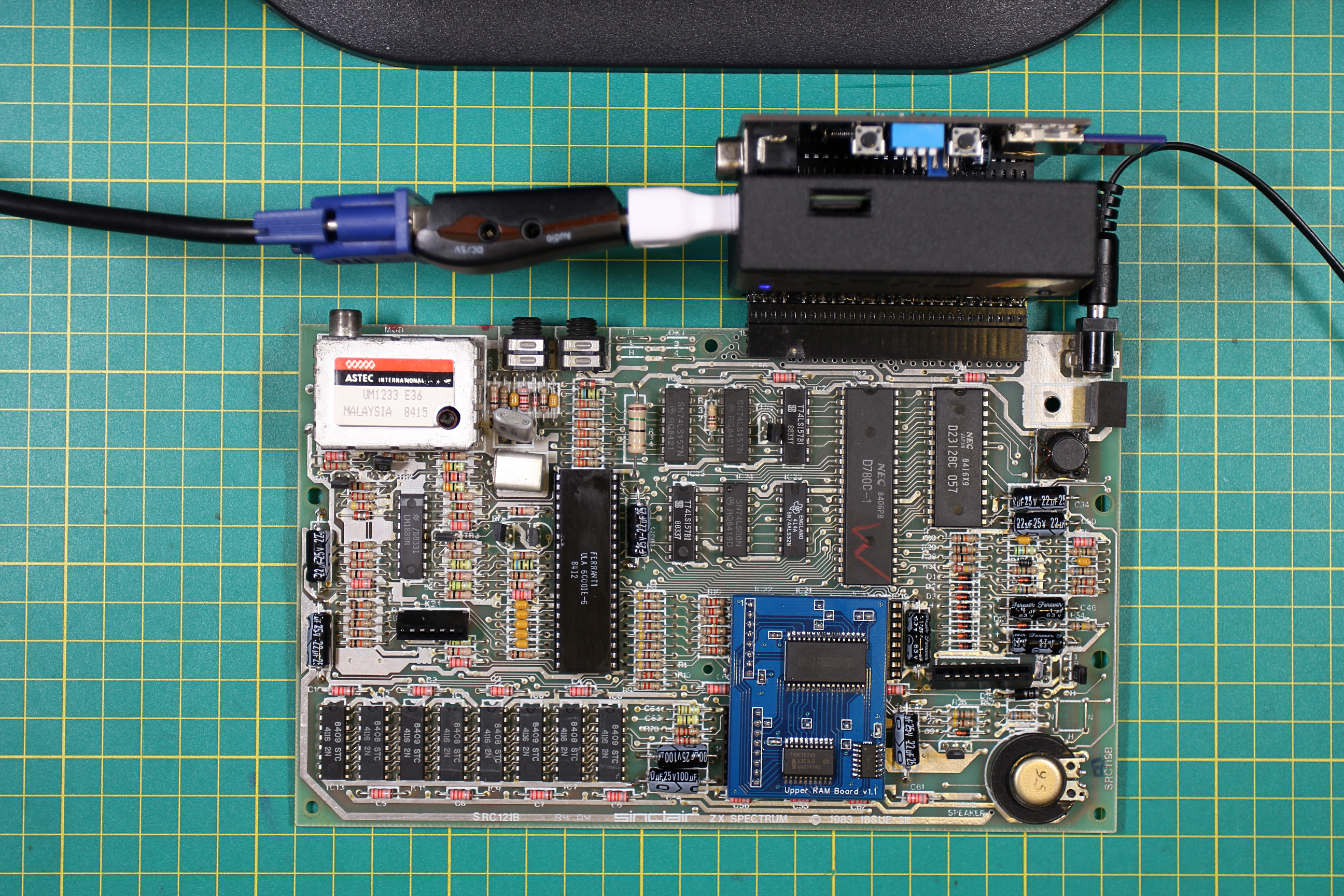
Testing the Board
I also stack a Retroleum Smart Card loaded with Brendan Alford’s diagnostic software behind the ZX-HD for testing. Trusting myself to have done a good job so far, I powered up the board and it passed all the tests with no issue. I usually leave the board running for a while in soak to check there are no temperture related problems. In this instance I left it cycling tests for half an hour or so.
Having successfully repaired the RAM, Re-Capped and replaced the regulator, it was time for the next step, the Composite Video Mod.