A short while ago, I became reaquainted with the world of the Sincclair Spectrum. Back in the original Spectrum Heyday, I had many bits and pieces (wish I’d have kept them!) one of which was a composite monitor. In fact, I think it was a Microvitec Cub. Now I have got another Spectrum and I am slowly getting back into machine code programming, I’d really like a better monitor than the 7in Car TV style unit that I’m using.
I found a bargain on eBay, a Dell UltraSharp 2007FP for just under £30. I connected it to the Spectrum on arrival and…. nothing. Well, the screen looks like its about to display and just switches off after briefly displaying a logo in the top left hand corner.
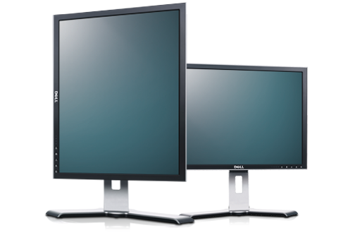
Dell UltraSharp 2007FP
It’s a lovely monitor with Composite, S-Video, VGA and DVi inputs, as well as a USB Hub built in. The display can even revolve and be used in portrait mode.
I spoke to Andrew Gostling in the Spectrum 4Ever group and he advised me to change the composite mod I had carried out on my Spectrum from the transistor type to the capacitor type. I did so but Dell still did not want to know. Andrew also suggested I try an inverted emitter follower circuit. I didn’t have the chance to do this until now.
Please Note: If you choose to follow these instructions, you are solely responsible for any and all damages and/or injury caused. If you are not confident with a soldering iron and de-soldering equipment, you would be better to find someone with the correct experience. Having said that, it isn’t a hard procedure and, if done properly, it can also be reversed with relative ease. So, in short, these instructions assume a certian level of competence with regard to electronic assembly and it is not meant to be a tutorial as such.
You will need the following components:
- 1x 100R Resistor
- 1x 100uF Electrolytic Capacitor
- 1x PNP BiPolar Transistor (I chose a 2N3906)
Rather than change the Spectrum I had already modded twice, I elected to add the new composite mod to my spare Spectrum Plus board which needed a refurb anyway. Unfortunately, the case for this Issue 6B board has a few screw pillars missing and the keyboard membrane is also shot. This is why I’ve been keeping it as a spare.
The first step was to add the composite mod. I carefully disconnected the +5v and Video Input lines and folded them over the side of the modulator case after removing the friction fit cap. Also, disconnect the resistor from the phono socket on the back of the modulator. Tidy this up since we will be connecting to it in a moment.
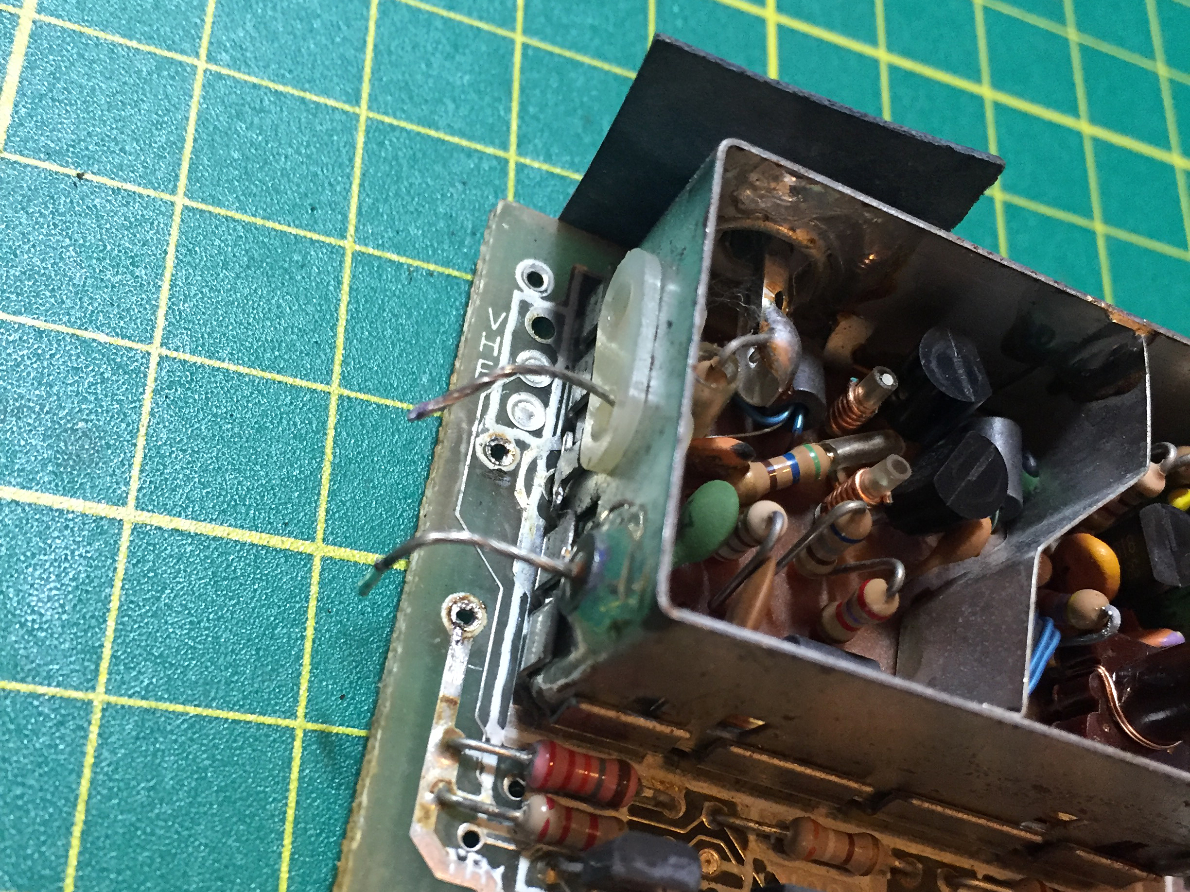
+5Volts and Video Disconnected
Connections Folded Over
After having disconnecting the original lines, which effectively disconnects the modulator circuit, it was time to add the composite mod itself. First, check the holes that were where the +5v and Video lines were, then clear the hole near the back edge of the board. If you turn the board over, you will see which one is connected to the Ground Plane, that’s the one to clear.
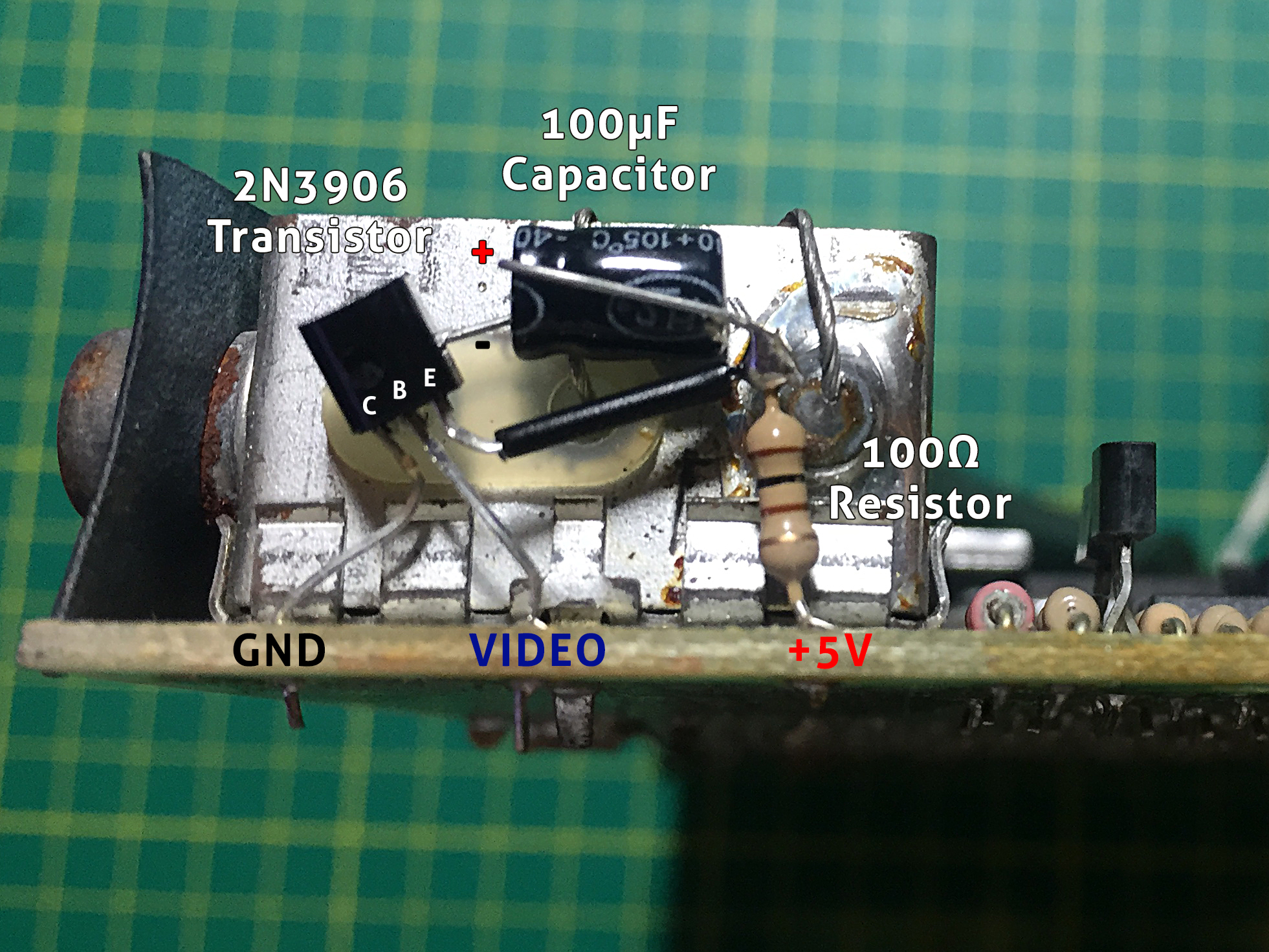
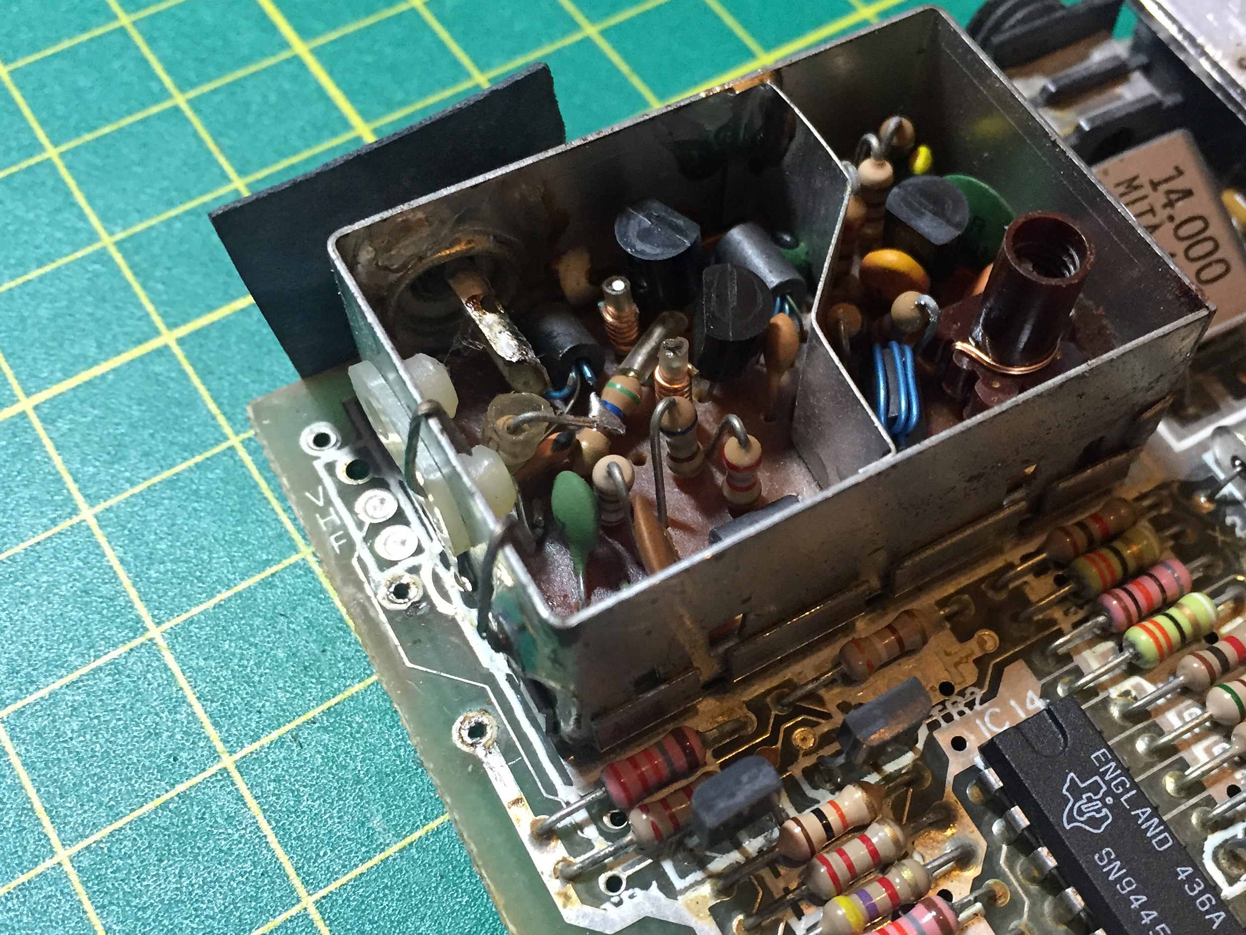
Inverted Emitter Follower Composite Mod
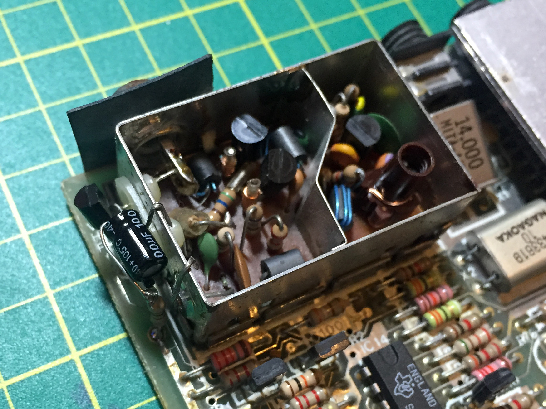
Composite Mod Overview
I connected the transistors Collector and Base first to provide a foundation to work on. In this instance, I chose a 2N3906. The configuration of the transistors leads means that you should face the flat side towards the modulator case. If you choose a different transistor, fit accordingly. Next, I connected the 100R resistor to the +5V connection on the board and connected the other end to the emitter of the transistor. I put some sleeving on the emitter leg to prevent it shorting against the modulator case, however after adding the capacitor next, it probably was safe enough.

Video Mod Schematic
I next carefully bent the transistor out of the way and connected the negative lead of the capacitor (which should be clearly marked on it’s body) to the video output center, feeding the lead through the unused plastic port on the modulator. The other end (positive) connects to the junction of the resistor and the transistor’s emitter lead. Hopefully, this is all apparent from the images above.
Before trying the mod out, I felt it was a good time to exchange the LM7805 linear regulator for a TRACO TSR 1-2450 which is a small pin-for-pin substitute. It is a switch-mode unit and is very efficient, far more so than the 7805. It also dispenses with the metal heatsink.

LM7805 Heatsink Removed
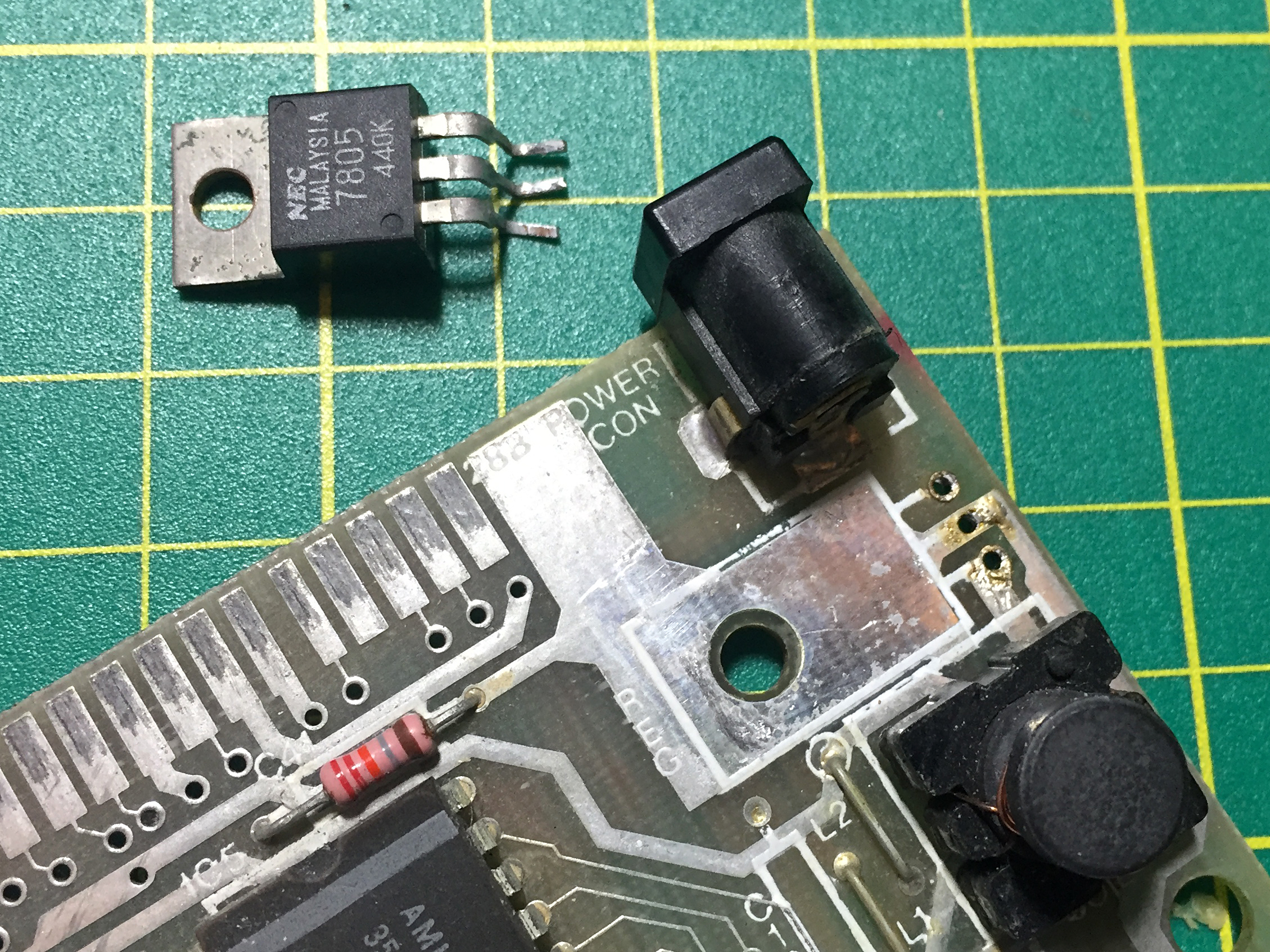
LM7805 Removed
The TRACO unit is a drop in replacement and is easy to solder in. I used a little blu-tak to hold it in whilst I soldered it in place.
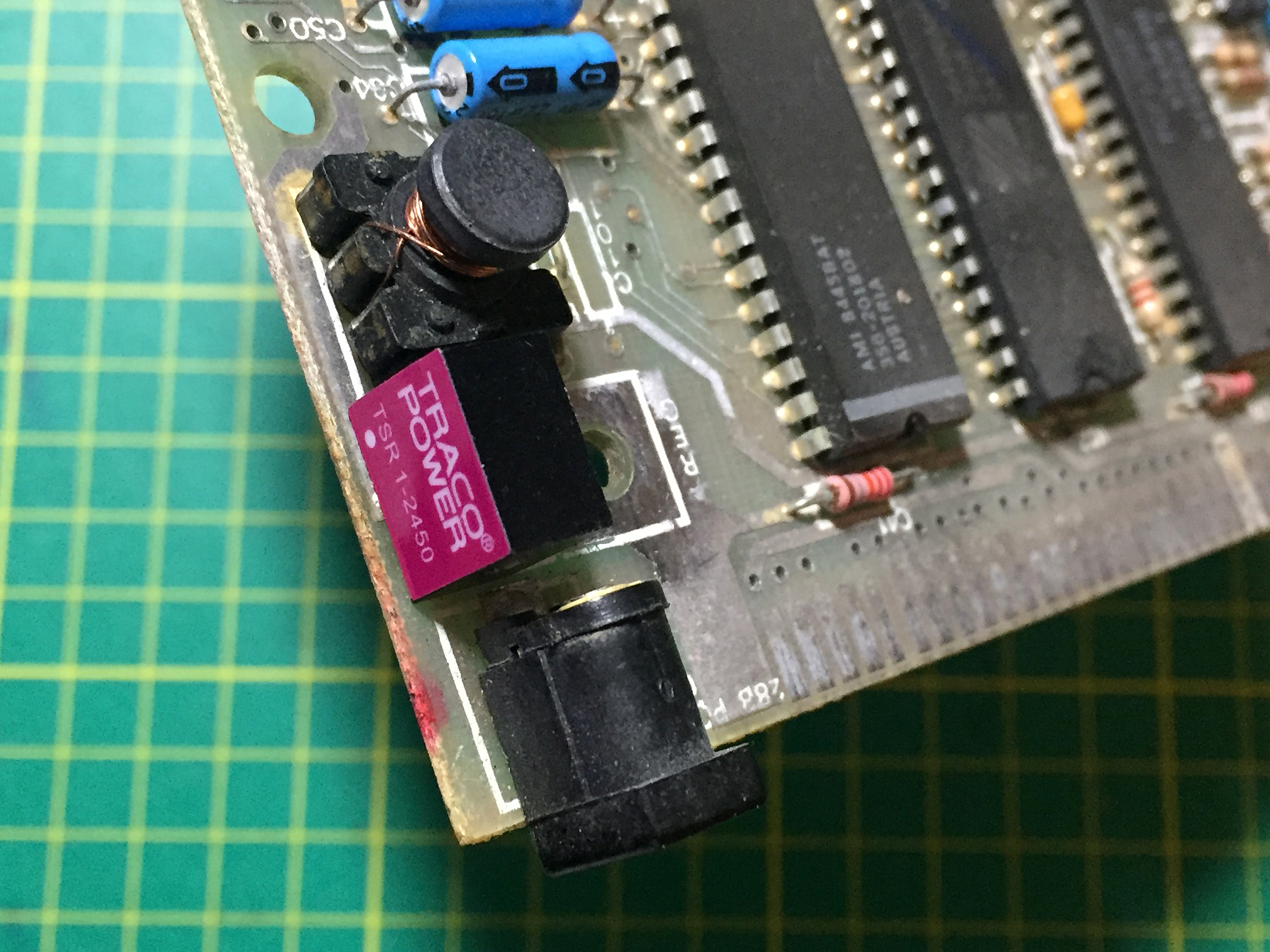
TRACO Regulator Soldered In Place
I’m very pleased with this particular mod. I ran the board for over an hour afterward and the TRACO unit doesn’t even warm up.
The time had come to try the monitor out but, since it would mean clearing the workbench, I decided that I’d re-cap the board first. This involves getting a re-capping kit from someone like the brilliant Retroleum or sourcing the correct capacitors yourself. I had a spare set from Retroleum so they got used. I carefully removed the old capacitors one by one, noting what value they were and what orientation they were in and replacing them with the new ones. I make it a point to face the values upward to ease future repairs/replacments.
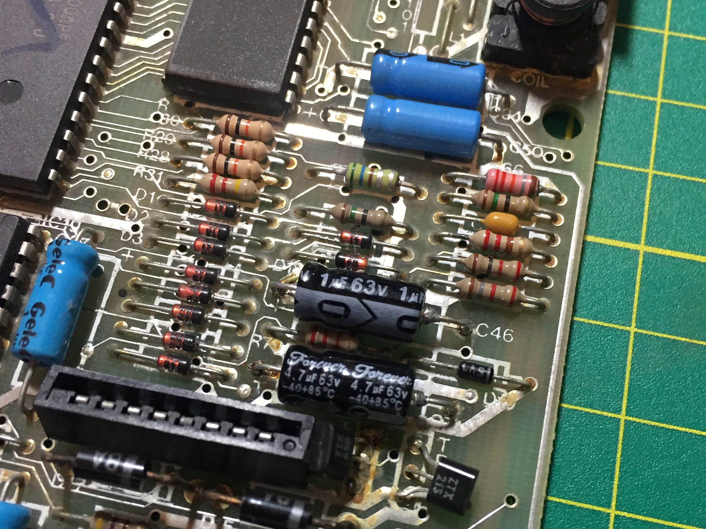
Two Capacitors Replaced
Having finally completed this task, I connected the Spectrum up to the monitor, powered up and… still nothing. Well, I think the monitor is extra picky about it’s composite input. I have spoken again to Andrew and he recommends I try connecting to the S-Video socket. I have ordered a cable that I can modify with a phono connector to provide the correct connection.
Meanwhile, I have a working refurbed Spectrum Issue 6b board and the composite mod does work on my 7 inch car style monitor.
Many thanks to Andrew Gostling for his continued assistance.