All the excitement around the Spectrum Next Kickstarter, and now the shop opening on the forum got me inspired to get hold of an original machine on eBay. Supposedly in working condition, it arrived with a problem.
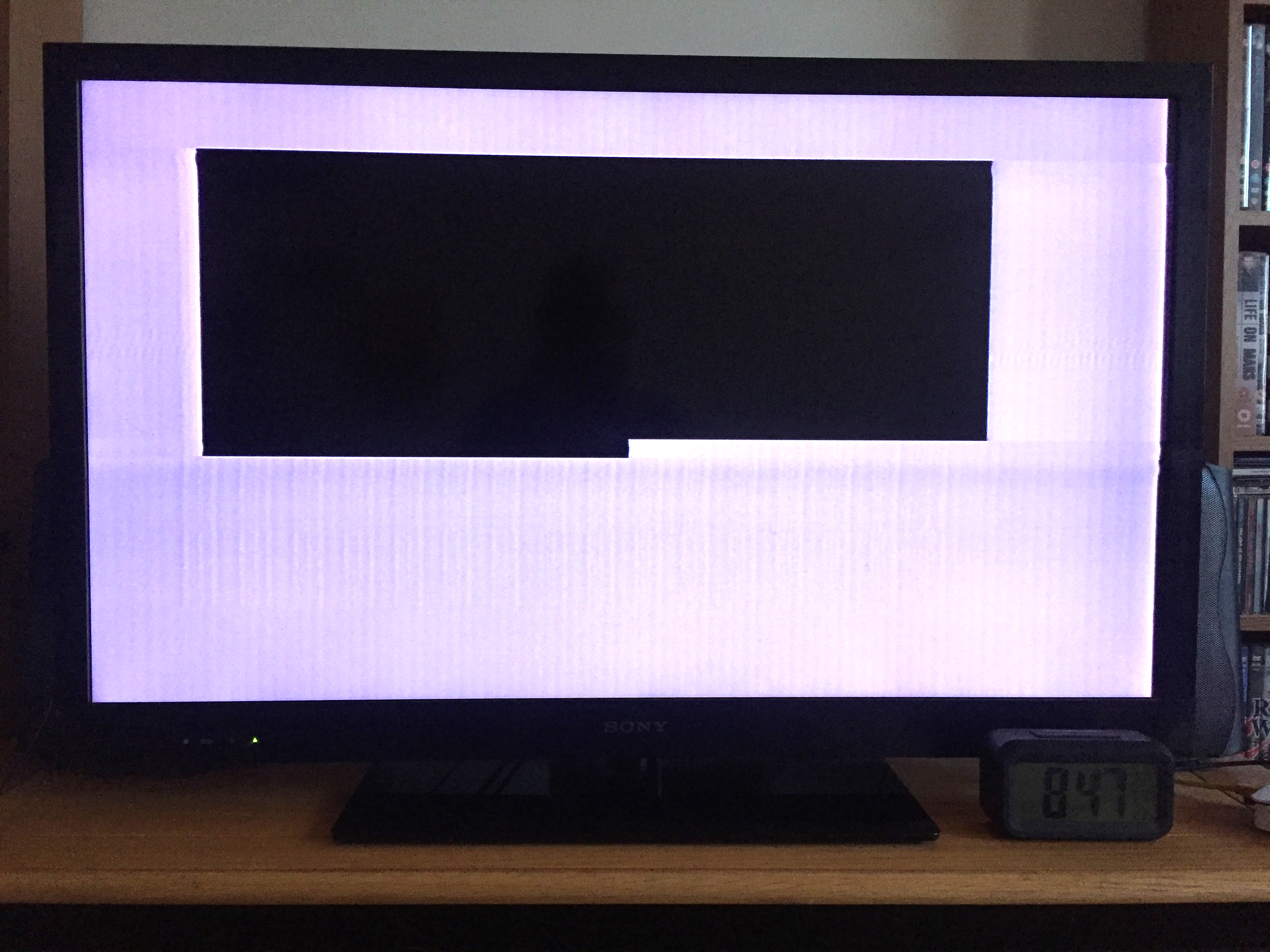
Spectrum RAM issue
The eBay seller apologised profusely and requested I send the machine back and have a full refund, however, I know my way around a circuit 😉 so I kept it. The eBay seller kindly gave me a partial refund. I was pretty sure what the problem was from how the display was and the exchange I had with the seller. It looked like a RAM issue.
Since I was intending to use the machine for programming and such, I had decided to fix it sooner rather than later. I ordered a ZX SpectROM with Diagnostic software specially supplied to narrow down the problem.
Upon powering the machine up with the ZX SpectROM installed on the rear expansion port, the Spectrum bleeped 8 times and then went on to have it’s RAM checked. All the lower RAM passed, the upper RAM failed every test!
I ordered a couple of upper RAM modules from Phil at Retroleum Whilst I was ordering, I got a couple of re-capping kits too! They duly arrived and I went about fitting the capacitors first. however, before fitting, I gave the board a once over and found a connection un-soldered!
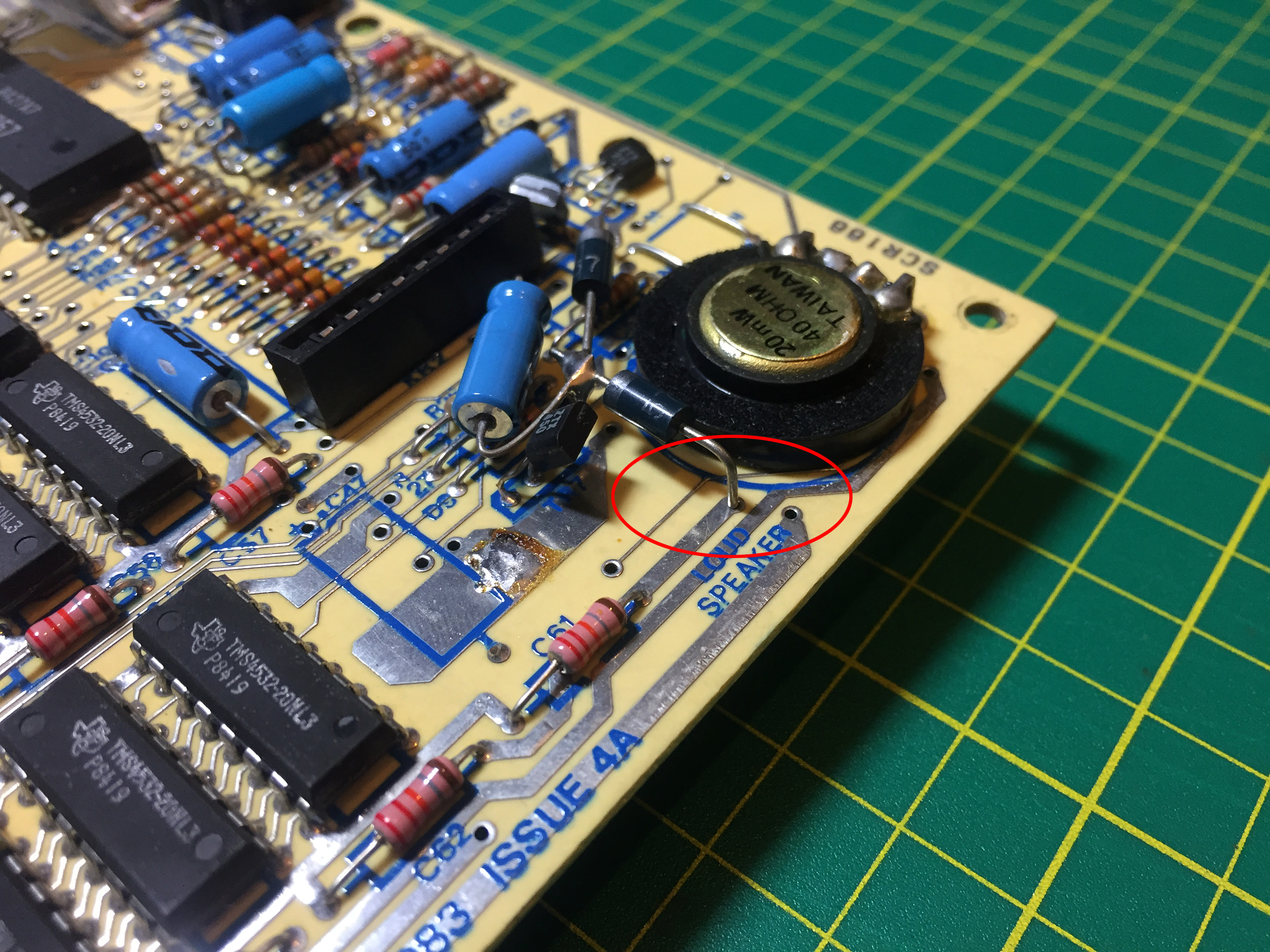
Ooops, someone missed this!
It was completely clean, as if it had been in this state from factory! Needless to say, I rectified the problem before proceeding to replace the capacitors. I made a special effort to face all the values upwards so that they can be read in the future.
After re-capping, I had to remove all the upper RAM chips to make way for sockets. This would be primarily for the new RAM module but it’s nice to have the facility to fit original RAM should I choose to sometime in the future.
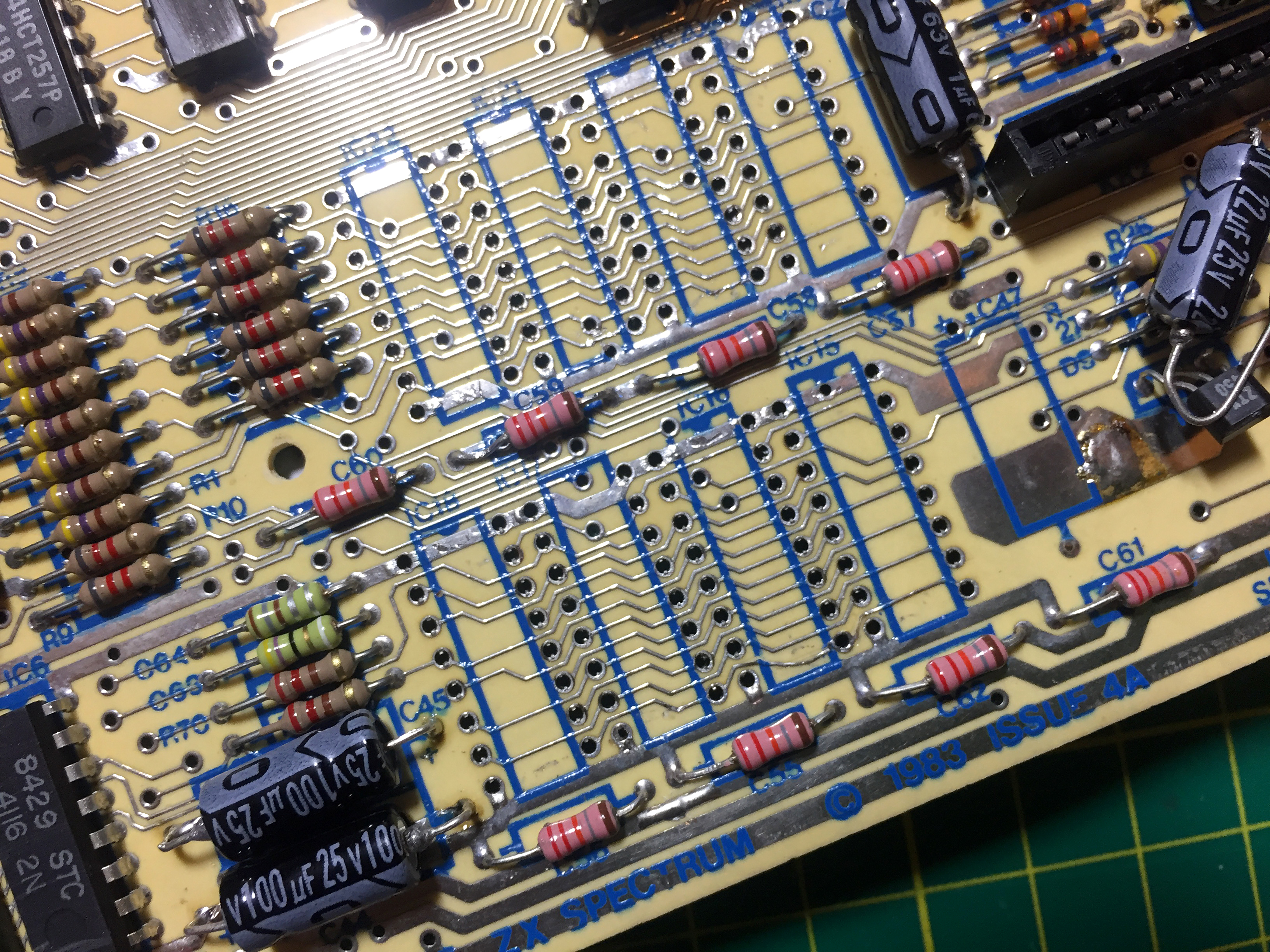
Upper RAM removed
Eagle-eyed among you might spot a dodgy track on the lower right-hand pair of chip placements. Careful as I was, I still had that one track lift. However, despite how it looks, it didn’t break. I managed to get it back into place before soldering the sockets over the top.

Sockets installed
With the sockets installed, it was time to fit the RAM module. This went on very easily. You just have to line up the top left pin with the top left socket and the bottom right pin with the bottom right socket. The module fitted in very firmly. I double checked I’d got it in the right place.
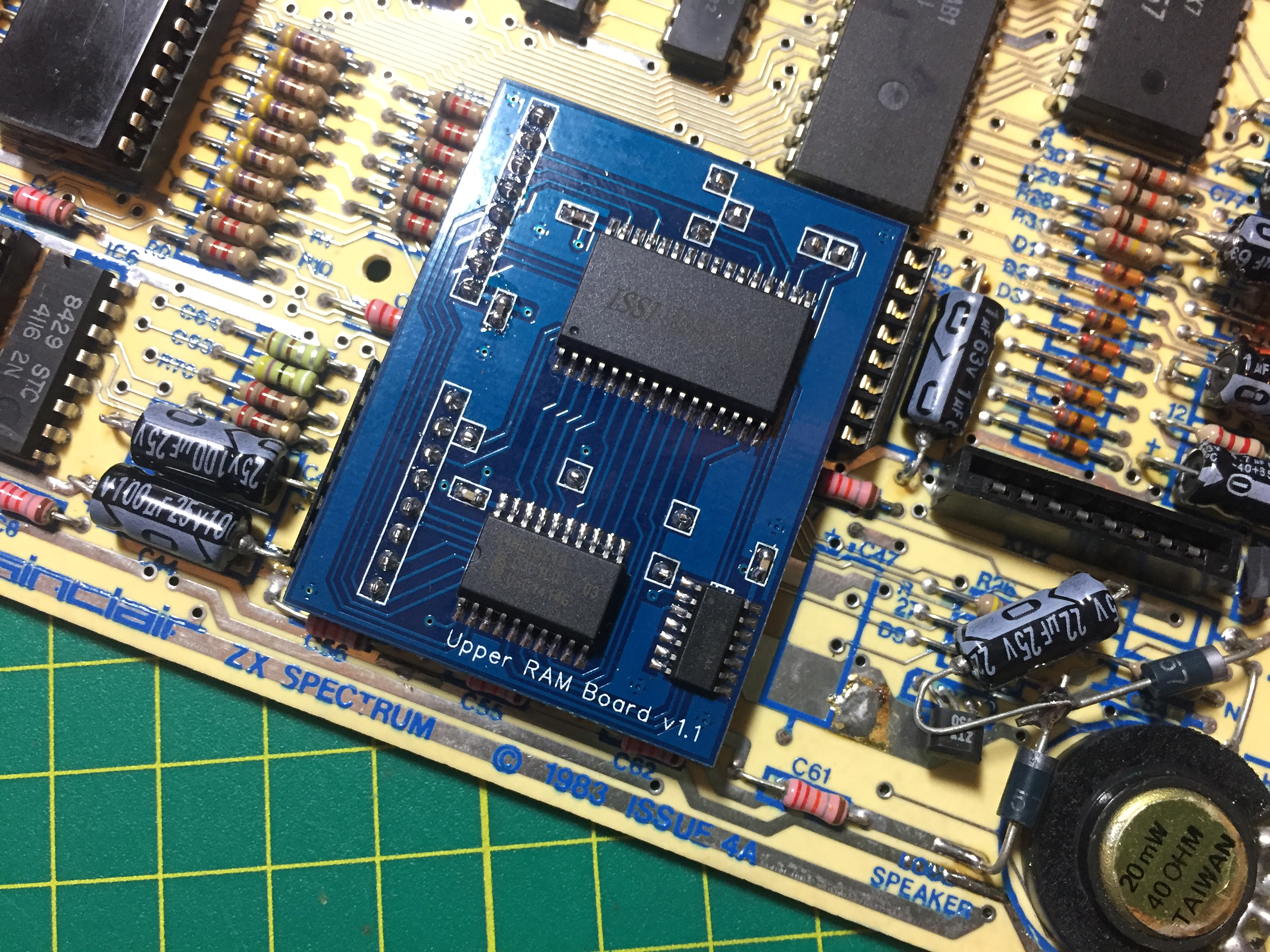
New Upper RAM Module Fitted
Since I was in the machine and the components came with the re-capping kit, I chose to perform the composite video modification as well as the re-capping and RAM replacement. This is another simple procedure.
Two options are available and Phil includes components for both with the re-capping kits. The mod can be done with a capacitor or a transistor. I chose the transistor mod because that also provides a buffer for the Spectrum’s video circuitry.
First the internal connection to the output socket is de-soldered and folded out of the way. Then the power and feed lines to the modulator are disconnected and folded over the can’s edge and finally, a transistor is soldered in place and a connection made from the pin nearest the rear of the Spectrum up and through the modulators case to the output socket.
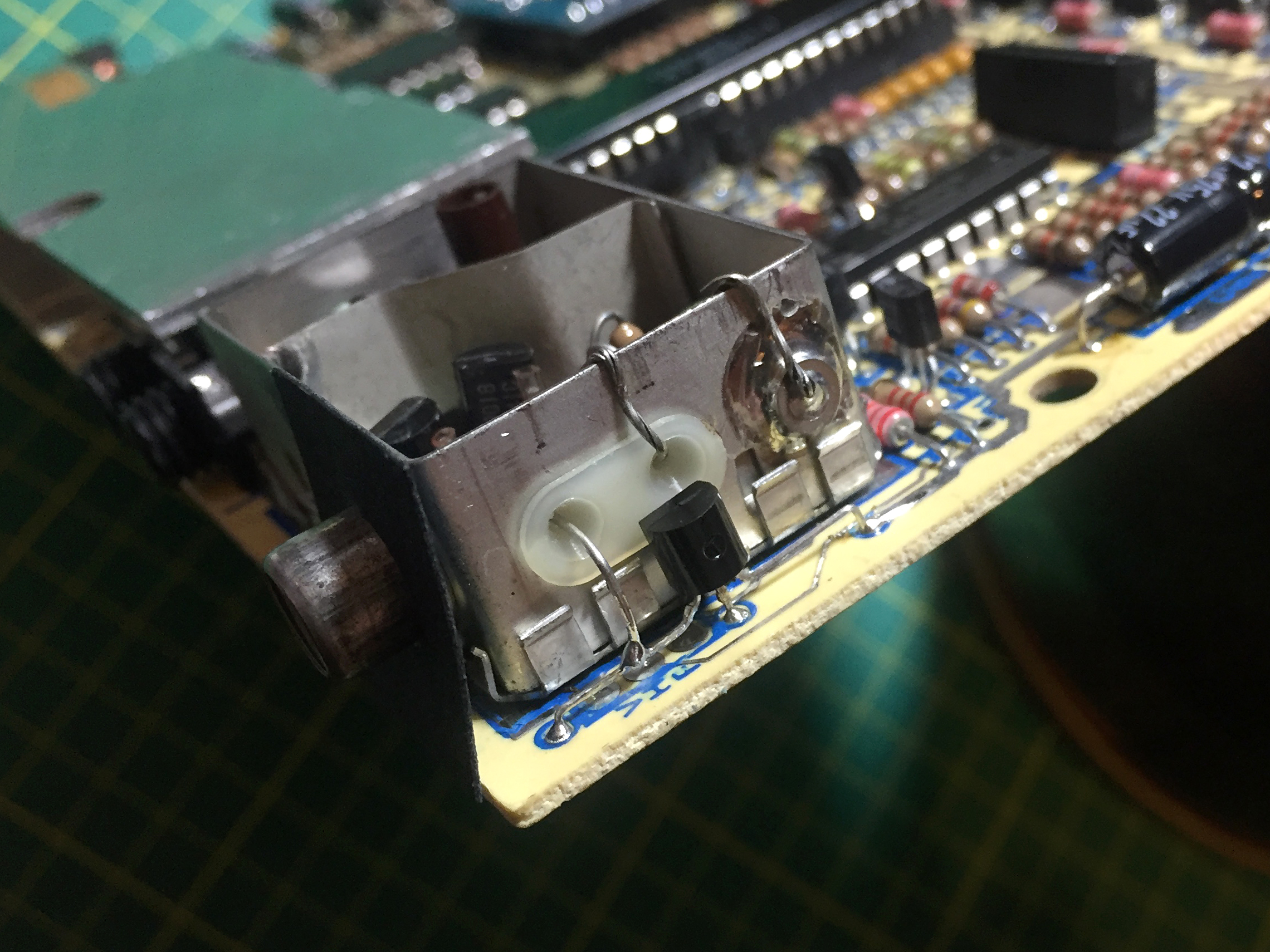
Composite Mod Transistor

Composite Mod From Above
After carrying out all this work (and having a much needed cuppa!) I did a final check around the board, particularly in areas I had worked in. All seemed OK so I replaced the board in the ‘Plus’ case, screwed it up and plugged it into a 7-inch composite monitor. I was greeted with the ‘© 1982 Sinclair Research Ltd’ message. Yay! I’d fixed it.
I really enjoyed the experience too. Buoyed by this, I built a DivIDE interface for storage and convenience. Unfortunately, the board does not didn’t work.
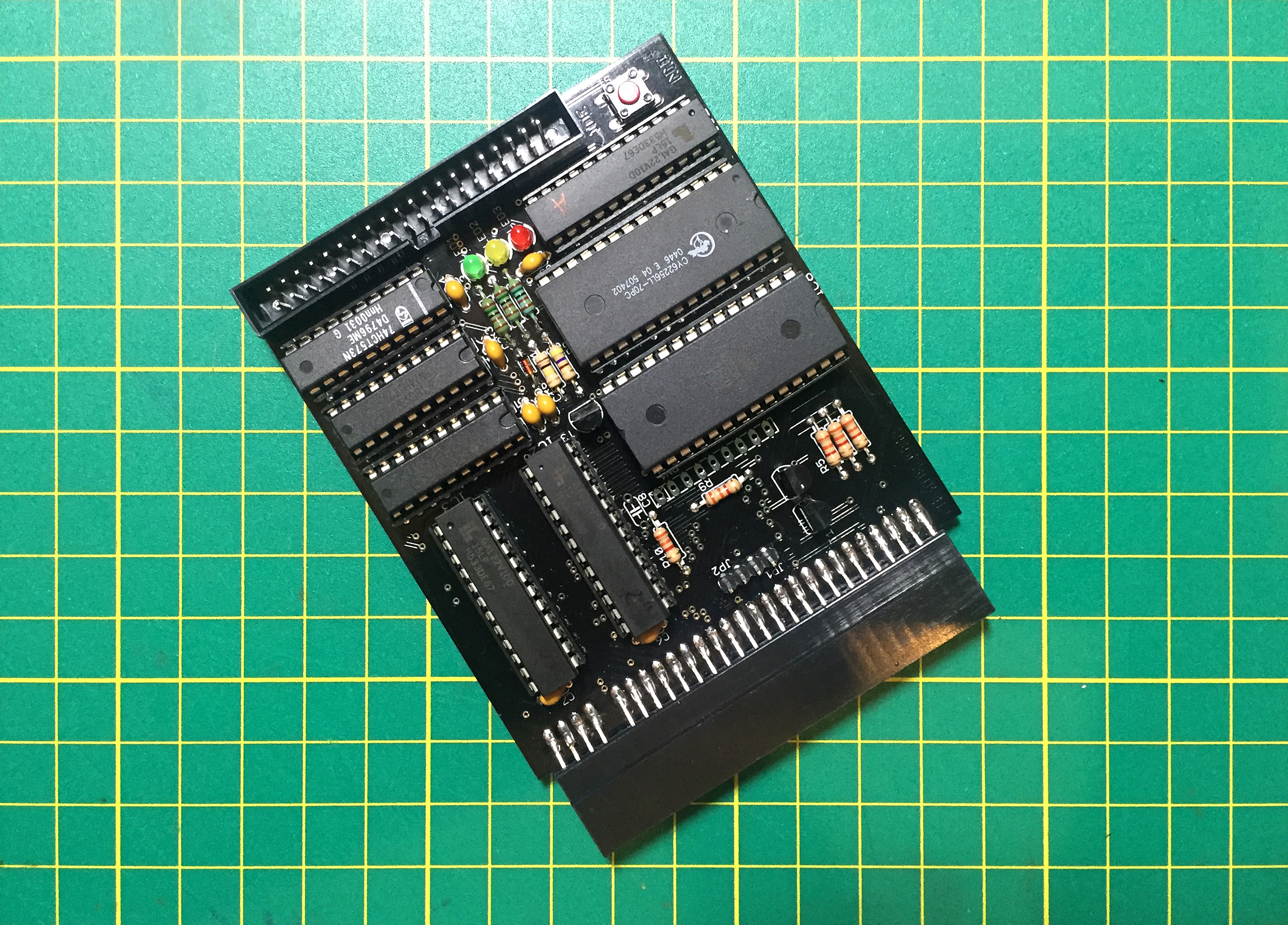
DivIDE 57c
I take great care when I build anything and I double checked the connections. All seemed fine. I checked the ROM and GALs had data programmed into them with a Minipro TL866 but later, loaded EXSDOS since that’s what I will be using when the Spectrum Next arrives. Updating the ROM had no effect. Pressing the NMI button just reset the Spectrum.
I had a chat with some of the guys on the Spectrum 4 Ever group on Facebook and the consensus was that the Z80 chip probably had a weak/faulty M1 line. I reopened the case, de-soldered the Z80 and replaced it with a socket. I then tried 3 other Z80 chips, all of which even failed to react to the NMI button at all. I suspected there is an issue on the DivIDE board or that the Z80’s I substituted all had M1 issues. I continued to work on the issue.
In the meantime, I’d found a couple of cassette tapes of utililties and machine code that I wrote in 1991! I’ve begin to transfer them over to PC so I can re-learn what I knew back then.
[UPDATE]
I dug out the ZAViouR board to see if I’d left a Z80 on it. I had, and one substitution later, I had a working DivIDE! So, this confirms, I have four Z80s with weak or faulty M1 lines. I have marked them clearly and will only use them in projects that don’t require the M1 line!