Lately, I’ve been distracted from general AVR stuff by the now ubiquitous ESP8266. I purchased a few ESP-01 boards and an ESP-03 board a while before moving location and I’ve just got around to learning a little about them.
The first thing I did was rig up a small strip board PCB to aid in the programming. At first, I was powering the ESP module from the USB to Serial adaptor but I found that it wasn’t man enough. I modified the board to accept external power from my bench PSU and disconnected the +3.3V line from the adaptor.

ESP-01 Prototype Programming Rig
This was just intended as a quick solution until I designed a proper PCB. Meanwhile, I discovered that you can use the Arduino IDE to program the ESP modules. I’m very familiar with the Arduino IDE so I installed the files required after downloading the latest Arduino software.
Having gotten interested in the ESP modules, I did some searching and one of the websites I came across was www.openhomeautomation.net Here was documented a way of logging Temperature and Humidity from a DHT11 unit connected directly to the ESP-01 module. You can see a DHT11 in the previous image in the top left of the PCB. I duly followed the instructions on the Cloud Temp/Humid Logger page and lo and behold, I had Temperature and Humidity values displayed on Freeboard (May not be up to date or accurate).
Although I had made the prototype configurable for programming and reading from the DHT11, I really wanted a dedicated board I could use, and one that would allow me to utilise the ESP-03 module that has lots of GPIO pins broken out. I set to work designing a board in Eagle.
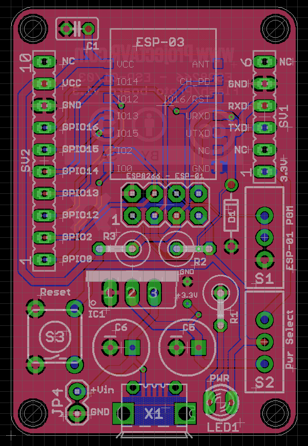
ESP8266 Flash Board v.1.3 Eagle Preview
This is the result. A general purpose board able to accommodate either the ESP-01 or ESP-03 modules. The power source is selectable from either the USB to Serial input header or a Micro USB connector/standard 0.1 pitch header. In the latter case, the voltage is regulated to 3.3V by the LM1117T device. The board also features a 3.3V zener diode on the RX pin of the modules to prevent over voltages over serial, a reset switch, power indicator LED and GPIO header.
Once the boards have arrived from the fabricator and I have checked them over, the design files will be available on a dedicated page licenced under Creative Commons Attribution – Share Alike v4.0 for anyone to use as they see fit.