The next step I had to take was to obtain or create a UV Exposure box. I had already had experience with one due to another interest but that model, while easily up to the task, was prohibitively expensive. I looked at a few other off-the-shelf models but I wasn’t willing to make such an outlay for a piece of equipment that would only be used occasionally.
I resolved to make one and started to do some research. My first thought was to use UV Fluorescent tubes but it wasn’t long before I came across designs using UV LEDs. LEDs have many advantages over fluorescent tubes. LEDs are tough and in general are less power hungry than tubes as well. I found some UV LEDs on eBay. 100 units for a few GB £s. I ordered two lots. I then went looking for a box. Again, eBay turned up trumps and I found an ideal pre-made wooden box. This was around £6 but it would cost me lots more in money and effort to make one. The last thing I needed, aside from some hook-up wire, was something to mount the LEDs on. Since the hole point of the excercise was to make PCBs, I wasn’t in a position to fabricate a layout so I ordered some strip board.
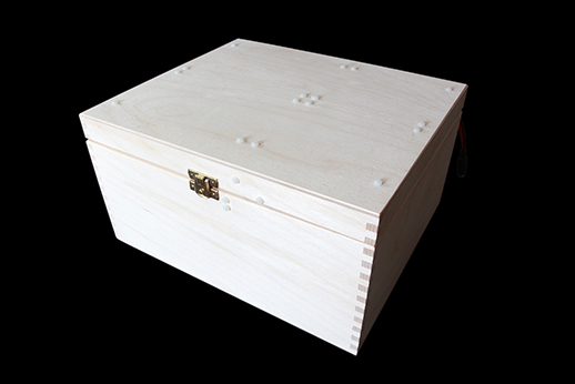
Box sourced from eBay
Once the parts arrived, I worked out, how much strip board I could fit in the lid and prepared the pieces accordingly. I then worked out, how many LEDs I could fit in equidistantly. I had a 9V power supply with enough uuumph! (Power) to supply a matrix of LEDs direct so I divided tracks up on the strip board to accommodate this. Each LED required 3V so three in series would be 9V. I divided across all of the boards and worked out where the links would need to be.
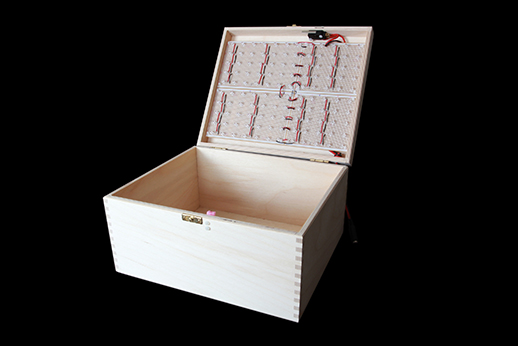
The open UV Exposure box revealing the safety switch and matrix of LEDs.
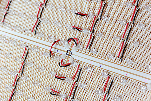
Close up shot of the LED matrix.
Whilst wiring all this up, I remembered that UV Light can be harmful. I’m not sure exactly how much damage these small devices could do but I wasn’t going to take any chances. I have heard tales of people being blinded by CD Rom LEDs so I thought it best to be safe. What I did was to engineer a safety cutout switch on the lid so that if the lid was opened during an exposure, the LEDs would immediately be extinguished. I found a micro-switch and bolted it to the front of the box.
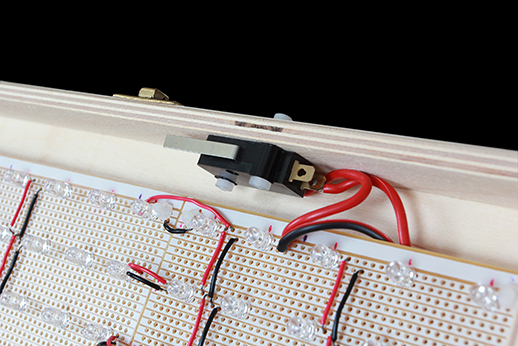
UV Exposure Box Safety Switch on the lid of the box.
I then bolted a soft block of sponge on the opposing side to trip the switch. When closed the switch completes the power circuit, and when open, it breaks the connection.
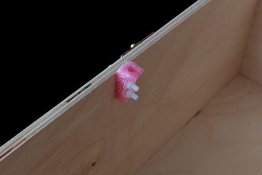
UV Exposure Box Safety block.
The last step was to feed a power line out which I did at the lower side of the lid. This is plugged into the output of the timer. I was going to design a timer and build one on strip board but I came across a timer kit from Evil Mad Scientist which would do the job. I ordered this and once arrived, I built it and housed it in a box I had lying around.
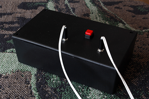
UV Exposure Box Timer from Evil Mad Scientist
The timer is set to 3 minutes which I have found to be optimum for the process that I use. The timer board has DIL switches to set the time, although these could be made in a different fashion if you wanted complete control over the time value. The power for both the timer and the LEDs is fed into the left hand socket and the timed power emerges from the right and all that’s needed is to press the switch to initiate the exposure.
Next time, I’ll explain a simple exposure frame for transparencies and PCB material.
Please Note: UV (Ultra Violet) Light is harmful. It is not advisable to look at or be exposed to UV Light. If you choose to build a project like this, take sensible safety precautions and always face UV Light Sources away from yourself and others (this includes animals!) before applying power.